for the quantitative analysis of landscape structure
Version 2.2
December 1, 1997
GRASS 5.0 r.le version (2001)
William L. Baker
Department of Geography and Recreation
University of Wyoming
Laramie, Wyoming 82071 U.S.A.
(307)-766-2925
This set of programs was developed in part with funds from U.S. Department of Energy Grants DE-FG02-89ER60883 and DE-FG02-90ER60977. This support does not constitute an endorsement by DOE of the views expressed in this document.
TABLE OF CONTENTS
1. INTRODUCTION .....................................................  3

	1.1.  Purpose of the r.le programs .............................  3

	1.2.  Relationship of the r.le programs and GRASS ..............  4

	1.3.  Overview of the r.le programs ............................  5

2. THE r.le PROGRAMS ................................................  5

	2.1.  Operation ................................................  5

	2.2.  Data input ...............................................  6

 		 2.2.1. A caution about "0" data .......................  6

 		 2.2.2. The GRASS mask .................................  7

	2.3.  The r.le.setup program ...................................  7

 		 2.3.1. Sampling .......................................  8

 		 2.3.2. Group/class limits .............................. 14

 		 2.3.3. Color table ..................................... 16

	2.4.  Syntax for the r.le analysis programs ..................... 17

	2.5.  The r.le.dist program ..................................... 17

		 2.5.1. Syntax for the r.le.dist program ................ 18

		 2.5.2. Examples of the use of the r.le.dist program .... 21

	2.6.  The r.le.patch program .................................... 23

		 2.6.1. Syntax for the r.le.patch program ............... 23

 		 2.6.2. Examples of the use of the r.le.patch program ... 30

	2.7.  The r.le.pixel program .................................... 32

		 2.7.1. Syntax for the r.le.pixel program ............... 32

		 2.7.2. Examples of the use of the r.le.pixel program ... 37

	2.8.  Output from the r.le analysis programs .................... 38

 		 2.8.1. Moving window output maps ....................... 38

 		 2.8.2. Output files and data formats from non-moving

 				 window analyses ........................ 39

			  	 r.le.dist .............................. 39

				 r.le.patch ............................. 39

				 r.le.pixel ................................. 42

				 The "out=" parameter and its output files .. 42

 		 2.8.3. Data analysis with external statistical

  				 and graphics software ...................... 43

	2.9.  The r.le.null program ................................... 43

	2.10. The r.le.rename program ................................. 44

	2.11. The r.le.trace program .................................. 44

3. GLOSSARY ......................................................... 46

4. BIBLIOGRAPHY ..................................................... 48

5. TABLES ........................................................... 51

	Table 1: Measures that can be calculated by the r.le programs.. 51

	Table 2: Measures whose output value, using a moving window,

		is a multiple of the real value ......................... 54

6. FIGURES .......................................................... 56

	Fig. 1: Sampling frame, sampling units, and mask .............. 56

	Fig. 2: The four kinds of sampling areas ...................... 57

	Fig. 3: An example of a moving window map ..................... 58

	Fig. 4: An example of an "interior" (core area) map ........... 59

	Fig. 5: Four different methods of measuring distance .......... 60

	Fig. 6: Seven different methods of measuring texture .......... 61

7. APPENDICES ...................................................... 62

	1. Limits ..................................................... 63

	2. Time needed to complete analyses with the r.le programs .... 64

	3. Examples of r.le.setup files ............................... 65

	4. Common problems with installing and running the r.le prog. . 67

	5. Help menus for the r.le programs ........................... 68
1. INTRODUCTION
1.1. Purpose of the r.le programs
Since the 1970s, with the availability of satellite data, there has been an increasing interest in the structure of the earth on the scale of kilometers or hundreds of kilometers. Landscape ecology is a multi-disciplinary pursuit, involving geographers, biologists, sociologists, remote sensors, and many others. The focus of landscape ecology is on the dynamics and structure of the biosphere, including human activities, on the scale of hundreds of meters to kilometers (Risser et al. 1984; Forman and Godron 1986; Urban et al. 1987). The science of landscape ecology expanded rapidly in the 1980s, and methods for the quantitative analysis of landscape structure also were developed (e.g. Mead et al. 1981; Gardner et al. 1987; Krummel et al. 1987; Milne 1988; Griffiths and Wooding 1988), yet there is no generally available software for the quantitative analysis of landscape structure that will work within a geographical information system (GIS).
The r.le programs have been designed to provide software for calculating a variety of common quantitative measures of landscape structure. The programs can be used to analyze the structure of nearly any landscape.
1.2. Related software (SPAN & FRAGSTATS)
There are two main programs available that also can be used to calculate landscape level indices. The first main program is SPAN (Turner 1990). SPAN was developed for landscape ecological analyses and has been widely utilized. It offers a set of measures related to cover, edge, size, fractal dimension, adjacencies, diversity, and texture. SPAN is a stand-alone program not integrated inside a GIS and it has a more limited set of measures than either FRAGSTATS or the r.le programs. It has been distributed by Monica Turner at Oak Ridge National Laboratory.
The second main program is FRAGSTATS (McGarigal and Marks 1994). This software is available over the Internet (ftp.fsl.orst.edu or IP number 128.193.112.107). FRAGSTATS has several advantages and limitations compared to the r.le programs. I want to spend a little time comparing the r.le programs and FRAGSTATS because they both may be useful to users, but also because we of course believe the r.le programs to be a little better, although FRAGSTATS is a good program as well.
First, FRAGSTATS is available for use with ARC/INFO and it also accepts data in several raster forms (ASCII, 8/16 bit binary, ERDAS image files, and IDRISI image files). The program runs on UNIX workstations or a PC. GRASS users would need to output their data as an ASCII or binary file for reading into FRAGSTATS. The r.le programs can of course also be used to analyze data from ERDAS, ARC/INFO, or other systems. The GRASS r.in.erdas, i.in.erdas, v.in.arc, v.in.ascii, r.in.sunraster, and r.in.tiff programs can be used to import data from other sources prior to the use of the r.le programs. The public domain program, XV, is also useful for transferring among different image formats. FRAGSTATS has procedures for calculating measures related to size, density, edge, shape, nearest-neighbor distances, and contagion and interspersion.
Most of the indices in FRAGSTATS are also available in the r.le programs or can be calculated from r.le output. The r.le programs have more indices for texture (e.g., angular second moment, etc.), a greater diversity of ways to measure patch-to-patch distance, three kinds of shape index measurement (one in FRAGSTATS), the dominance index that has been widely used in landscape ecology, and can measure edges by their type. FRAGSTATS has a richer array of core area metrics and an index called "proximity" (Gustafson and Parker 1992). FRAGSTATS also offers a nice feature for dealing with patches on the edge of a map. Otherwise there is considerable overlap in the indices available in the two programs.
The r.le programs offer a complex and flexible sampling overlay system that is useful in any analysis of irregular land areas. The user can distribute sampling areas over a part of the landscape, or calculate indices for separate, irregularly-shaped regions, or sample only in the vicinity of point observations (e.g., wildlife observations). FRAGSTATS operates only on the rectangular land area actually input to the program, although the user can code parts of this area for analysis. The r.le programs also can output new maps showing the location of particular types of edges and the sampling area framework. More significant, it is now possible to use the r.le programs to make a new map in which the original pixel attribute is replaced by a particular attribute (e.g., patch size) of the patch in which the pixel occurs. This is very useful in wildlife habitat modelling. Finally, in terms of sampling, the r.le programs allow the user to run a moving window of any size across the map to make a new map of landscape structure. This also is useful in wildlife habitat modelling.
Perhaps the most significant feature of the r.le programs, compared to FRAGSTATS, is that the r.le programs are imbedded in the GRASS GIS. Many features of GRASS offer powerful complements to the r.le programs. It is possible, for example, to immediately overlay a moving window output map from the r.le programs on top of a digital elevation model to illustrate how landscape structure varies across a topographic surface.
1.3. Relationship of the r.le programs and GRASS
The r.le programs are intended to be part of the Geographical Resources Analysis Support System (GRASS), a public-domain geographical information system (GIS), designed and developed through the Environmental Division of the U.S. Army Construction Engineering Research Laboratory in Champaign, Illinois (USA-CERL 1991). GRASS is primarily a raster-based GIS, but with extensive vector handling capabilities. GRASS requires the UNIX operating system, but can be used on a variety of workstations, as well as personal computers under LINUX and other flavors of UNIX. The r.le programs currently use GRASS version 4.1. Another version of the r.le programs is under development for use with GRASSLAND (L.A.S., Inc. 1997), a commercial GIS derivative of GRASS that runs under Windows 95 and NT. At the present time, only the r.le.dist, r.le.patch, and r.le.pixel programs will run under GRASSLAND. Further development of the r.le.setup and r.le.trace will take place, but requires considerable code-development using Tcl/Tk.
The r.le programs directly use the GRASS database, GRASS libraries, and the GRASS data structure in the calculation of measures of landscape structure, and use GRASS for the entry of digitized data. GRASS also provides a number of separate image processing, data manipulation, and mapping programs which can be useful for preparing data for analysis with the r.le programs and for displaying output. Most of these functions are also available in GRASSLAND (L.A.S., Inc. 1997).
1.4. Overview of the r.le programs
The r.le programs are designed for analyzing landscapes composed of a mosaic of patches, but, more generally, these programs are capable of analyzing
any two-dimensional raster or array whose entries are integer values. The r.le programs have options for controlling the shape, size, number, and distribution of sampling areas used to collect information about the landscape. Sampling area shapes can be square, or rectangular with any length/width ratio or can be circular with any radius. The size of sampling areas can be changed, so that the landscape can be analyzed at a variety of spatial scales simultaneously. Sampling areas may be distributed across the landscape in a random, systematic, or stratified-random manner, or as a moving window.
The r.le programs can calculate a number of measures that produce single values as output (e.g. mean patch size in the sampling area), as well as measures that produce a distribution of values as output (e.g. frequency distribution of patch sizes in the sampling area) (Table 1), and it is also possible to output tables of data about selected attributes (e.g., size, shape, amount of perimeter) of individual patches, as well as to make new maps of patch attributes. The programs include no options for graphing or statistically analyzing the results of the analyses. External software must be used.
The programs were developed on a SUN SPARCstation 1 workstation running the SunOS 4.1.3 operating system and the Open Windows 3.0 windowing programs, but have now been updated to operate under SunOS 5.5.1 (Solaris 2.5.1). The code is written in the C programming language and makes use of functions provided in the GRASS programmers' library (Shapiro et al. 1992).
2. THE r.le PROGRAMS
2.1. Operation
To run the r.le programs, the user must first start GRASS (type "grass4.1") and set up the working environment in GRASS by specifying the GRASS location and map layers to be used. The sequence of operations usually is to first use r.le.setup to set up a sampling framework (e.g., regions, sampling area size and shape, etc.) and then use the other r.le programs (e.g. r.le.pixel, r.le.patch, r.le.dist) to make the desired measurements. The r.le.setup program does not need to be run if the analysis will be of the full extent of the current GRASS region. All of the r.le programs operate from the GRASS command prompt (>). The commands and their parameters are entered after the GRASS command prompt, and the programs then go through a sequence of operations to complete the setup and measurements. Output from r.le.setup goes in the subdirectory "r.le.para" while output from the other r.le programs goes in the subdirectory "r.le.out". These subdirectories are created automatically when the programs are invoked, and are made subdirectories within the directory from which the programs are invoked. Some programs also can be used to make new maps, which become part of the maps stored in the current location and mapset (use "g.list rast" to see the names of raster maps).
2.2. Data input
The r.le programs work directly with map layers that have been input and preprocessed in GRASS. Data from Landsat Multi-Spectral Scanner (MSS) or Thematic Mapper (TM) or other satellites can be downloaded into GRASS using the image processing programs in GRASS. GRASS also has programs for reading files produced by ERDAS and ARC/INFO, and for reading ASCII raster files, TIFF files, and Sun raster files. Vector information can be input using the GRASS digitizing programs. Vector information must be converted to raster data using the GRASS program "r.poly" prior to using the r.le programs. Preprocessing capabilities of GRASS include programs to rectify imagery so that it matches a planimetric map and programs for classifying raw multi-band data.
The r.le programs were conceived for analyzing maps of patches. Any raster map can be considered to contain patchiness and can be analyzed using the programs, but a variety of landscape data can be more specifically considered "patch" data. Patches may be disturbance patches, remnant patches, environmental resource patches, introduced patches, or simply patchy entities on a map (Forman and Godron 1986). Patches may simply be landscape elements (Forman and Godron 1986), such as roads, dwellings, forest patches, grassland patches, hedgerows, or fields. Patches could also be types of forest in a forested landscape (e.g. deciduous forest, recently-burned forest, conifer forest), or types of grassland in a prairie landscape. Patches of different age occur in landscapes subject to disturbances (e.g. fires, floods), where the age of the patch represents the time since it was last disturbed. Patches could also be the types identified by completing a classification of spectral data in a Landsat image, or in a scanned aerial photograph. In general, patches are simply the result of grouping pieces of the landscape into units whose members share a common set of attributes.
2.2.1. A caution about "0" data
GRASS specifies that the integer "0" does not have the traditional meaning of zero. Instead "0" in GRASS means "no data." For this reason the r.le programs do not include "0" values in calculations. Raster pixels that contain "0" are excluded from all calculations and are skipped when the moving window is centered over them. If you have a patch that has the attribute "0" that you want to have included in the r.le calculations, you must recode it (use r.reclass) to some other attribute value (e.g., -999) prior to using the r.le programs. We hope that in future GRASS releases there will be a provision for the integer zero, which does on occasion have real meaning (e.g., age=0 for newly created patches).
2.2.2. The GRASS mask
GRASS has a mask command (r.mask) that can be used to limit the parts of a map that are included in an analysis. The r.le analysis programs do respond to a mask if it is present, and the results of analyses will be limited to the area specified as "1" in the MASK file. Moreover, when the moving window sampling method is used, the moving window will only move through the area of the map that is specified as "1" in the MASK file. This can considerably speed up the moving window operation, if the masked area is a small part of the map.
2.3. The r.le.setup program
The r.le.setup program is used to setup the sampling and analysis framework that will be used by the other r.le programs. The r.le.setup program is not yet part of the release for GRASSLAND (L.A.S., Inc. 1997). Before you run r.le.setup, be sure to back up files you already have made in the r.le.para subdirectory using r.le.setup in previous sessions, as the program will overwrite them! To run r.le.setup with GRASS do the following:
1. After starting GRASS and setting up your location and mapset, start a GRASS monitor window using the d.mon command.
2. Move the cursor back to the command window with the GRASS command prompt (>).
3. Type r.le.setup followed by a carriage return. This program runs only interactively.
4. You will now be queried for (1) the name of the map to be used as a backdrop for setting up the sampling scheme, (2) the name of a vector map to overlay on the raster map to aid in placing the sampling areas (optional), and (3) the name of a sitefile to overlay on the raster map to aid in placing the sampling areas (optional). These maps must already exist to be used here.
5. The raster map and overlay maps, if chosen, will be displayed and you will see the main r.le.setup menu.
The first menu allows the user to draw sampling regions, setup a sampling frame, setup sampling units or a moving window, setup limits for groups and classes, change the color table for the backdrop raster map, or exit and save the results of the setup.
2.3.1. Sampling
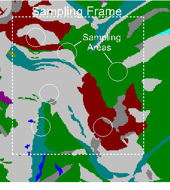
Information about the structure of the landscape is obtained by overlaying a set of sampling areas on top of a specified part (the sampling frame of a map layer, and then calculating specific structural measures for the part of the map layer that corresponds to the area in each sampling area (Fig.1).
To setup a sampling frame type 2 to "Setup a sampling frame." The program will ask "Will the sampling frame (total area within which sampling units are distributed) be the whole map? (y/n) [y]" Just hit a carriage return to accept the default (in brackets), which is to use the whole map. You actually do not need to setup a sampling frame if you want to use the whole map, as this is the default. To setup a different sampling frame type "n" and a carriage return in response to this question. Then use the mouse and a rubber band box to outline a rectangular sampling frame on screen. You will be asked last whether you want to "Refresh the screen before choosing more setup?" If you don't like the sampling frame you just setup, answer yes to this question, then type 2 ("Setup a sampling frame") again to redo this part of the setup. This sampling frame will be used to limit the spatial extent of all subsequent setup procedures.
A sampling area may be one of four things (Fig. 2). First, it is possible to treat the entire map layer as the one (and only) sampling area. Second, if the map layer can be divided into meaningful geographical regions (e.g., watersheds), then it is possible to treat the regions themselves as sampling areas. The third option is that the sampling areas may be sampling units of fixed shape and size (also called scale) that are placed within the map layer as a whole. The fourth and final option is that the sampling area may be moved systematically across the map as a moving window. The following sections present additional details about these options for sampling areas.
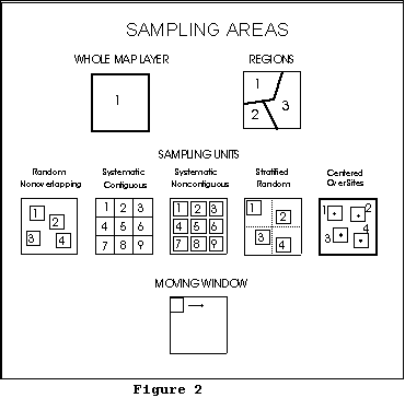
2.3.1.1. Whole map layer
If the whole map layer is to be used as the one and only sampling area (Fig. 2), then r.le.setup does not need to be run. The user may complete an analysis by simply entering the appropriate r.le command. The user can specify sam=w, but this is the default, so the sam= parameter can simply be omitted.
2.3.1.2. Regions
If regions are to be used as the sampling areas (Fig. 2), then the user can use r.le.setup to draw regions or any existing map of regions can simply be used directly. To draw regions and create a new regions map in r.le.setup select "Draw sampling regions" from the first r.le.setup menu, and the user is asked to do the following:
1. "ENTER THE NEW REGION MAP NAME:" Only a new raster map name is acceptable. The user can type LIST to find out the existing raster map names in this location and mapset.
2. "CHOOSE AN OPTION:"
Draw a region 1
Quit drawing regions and return
to setup options menu 2
Change the color for drawing 3
If you type 1 to "Draw a region" you will receive instructions on how to use the mouse to draw the region on the screen. Once the region is drawn, you can draw another region, start over, quit drawing and save the region map (or don't save it). You can also change the color for drawing, if you're having trouble seeing the boundaries you are drawing.
Once the "Quit drawing and save the region map" option is selected, the new raster map of the sampling regions is generated and displayed on the monitor window, and you are asked if you want to refresh the screen before choosing more setup. Note that you cannot draw regions in areas outside the mask, if a mask is present (see r.mask command).
The user can also use the GRASS r.digit or v.digit programs or the digitizing part of the GRASSLAND (L.A.S., Inc. 1997) map viewer to digitize circular or polygonal regions and to create a sampling regions map without using r.le.setup. Or, as mention above, an existing raster map can be used directly as a regions map.
2.3.1.3. Sampling units
If sampling units are to be used as the sampling areas (Fig. 2), then choose 3 for "Setup sampling units" from the first r.le.setup menu. The program checks the r.le.para subdirectory for an existing "units" file from a previous setup session and allows the user to rename this file (to save it) before proceeding. The r.le.setup program will otherwise overwrite the "units" file. Then the following choice is displayed followed by a series of other choices:
HOW WILL YOU SPECIFY SAMPLING UNITS?
Use keyboard to enter sampling unit dimensions 1
Use the mouse to draw sampling units 2
Which number?
When sampling units are defined using the keyboard, the user inputs the shape and size (scale) of the sampling units by specifying dimensions in pixels using the keyboard. When sampling units are drawn with the mouse, the user clicks the mouse to define the sampling units in the GRASS monitor window, and then actually places the sampling units for each scale onto the map. By placing the units with the mouse the user can directly determine the method of sampling unit distribution as well as the shape, size, and number of sampling units.
If the choice is made to use keyboard to enter sampling unit dimensions, the following series of questions must be answered:
How many different SCALES do you want (1-15)?
The user is asked to specify the number of scales that will be used. The r.le programs allow the user to simultaneously sample the same map with the same measures using sampling areas of different sizes. Currently there can be between 1 and 15 scales that can be sampled simultaneously. Substantial output can be produced if many scales are used.
Methods of sampling unit distribution
Sampling units must be placed spatially into the landscape. There are five options for doing this, but only one option can be chosen for each scale (Fig. 2):
1. Random nonoverlapping: Sampling units are placed in the landscape by randomly choosing numbers that specify the location of the upper left corner of each sampling unit, subject to the constraint that successive sampling units not overlap other sampling units or the edge of the landscape, and that they must be entirely within the area defined by the mask (see r.mask command) if one exists.
2. Systematic contiguous: Sampling units are placed side by side across the rows. The user will be able to enter a row and column to indicate where the upper left corner of the systematic contiguous framework should be placed. Rows are numbered from the top down beginning with row 1 of the sampling frame. Columns are numbered from left to right, beginning with column 1 of the sampling frame. A random starting location can be obtained by using a standard random number table to choose the starting row and column. The r.le.setup program does not avoid placing the set of sampling units over areas outside the mask. The user will have to make sure that sampling units do not extend outside the mask by choosing a particular starting row and column or by drawing a sampling frame before placing the set of sampling units.
3. Systematic noncontiguous: The user must specify the starting row and column as in #2 above and the amount of spacing (in pixels) between sampling units. Horizontal and vertical spacing are identical. Sampling units are again placed side by side (but spaced) across the rows. As in #2 the program does not avoid placing sampling units outside the masked area; the user will have to position the set of units to avoid areas outside the mask.
4. Stratified random: The strata are rectangular areas within which single sampling units are randomly located. The user must first specify the starting row and column as in #2 above. Then the user must specify the number of strata in the horizontal and vertical directions. As in #2 the program does not avoid placing sampling units outside the masked area; the user will have to position the set of units to avoid areas outside the mask.
5. Centered over sites: The user must specify the name of a sitefile containing point locations. A single sampling unit is placed with its center over each site in the site file. This is a useful approach for determining the landscape structure around points, such as around the location of wildlife observations.
Do you want to sample using rectangles
(Including squares) (y) or circles (n)? (y/n) [y]
If you choose rectangles, then the following series of questions must be answered:
Sampling unit SHAPE (#cols/#rows) expressed as a real number
(e.g., 10 cols/5 rows = 2.0) for sampling units of scale n?
The user is prompted to enter a ratio that defines the shape of the sampling units. Sampling units may have any rectangular shape, including square as a special case of rectangular. Rectangular shapes are specified by entering the ratio of columns/rows (horizontal dimension/vertical dimension) as a real number. For example, to obtain a sampling unit 10 columns wide by 4 rows long specify the ratio as 2.5 (10/4).
Recommended maximum SIZE is m in x cell total area.
What size (in cells) for each sampling unit of scale n?
The user is then given the recommended maximum possible size for a sampling unit (in pixels) and asked to input the size of sampling units at each scale. Sampling units can be of any size, but the maximum size is the size of the landscape as a whole. All the sampling units, that make up a single sampling scale, are the same size. After specifying the size, the program determines the nearest actual number of rows and columns, and hence size, that is closest to the requested size, given the shape requested earlier.
The nearest size is x cells wide X y cells high = xy cells
Is this size OK? (y/n) [y]
If you choose circles, then you will be asked to specify the radius, in pixels. Once you have addressed the questions associated with rectangles or circles, you can continue with the following questions:
Maximum NUMBER of units in scale n is p?
What NUMBER of sampling units do you want to try to use?
The maximum number of units that can be placed over the map, given the shape and size of the units, is then given. The user can then choose the number of sampling units to be used in the map layer. It may not always be possible to choose the maximum number, depending upon the shape of the sampling units. In the case of systematic contiguous and noncontiguous, the program will indicate how many units will fit across the columns and down the rows. The user can then specify a particular layout (e.g., 6 units could be placed as 2 rows of 3 per row or as 3 rows of 2 per row).
Is this set of sampling units OK? (y/n) [y]
Finally, the set of sampling units is displayed on the screen (e.g., Fig. 1) and the user is asked whether it is acceptable. If the answer is no, then the user is asked if the screen should be refreshed before redisplaying the menu for "Choose method of sampling unit DISTRIBUTION" so that the user can try the sampling unit setup again.
If the choice is made to use the mouse to draw sampling units, then the following menu for use with the mouse is displayed after you specify the number of scales and whether rectangles or circles will be used:
Draw a standard (rectangular/circular) unit of scale n.
First select upper left corner, then lower right:
Left button: Check unit size
Middle button: Upper left corner of unit here
Right button: Lower right corner of unit here
The user can then use the mouse and the rubber band box to outline the standard sampling unit. Once it has been outlined, the number of columns and rows in the unit, the ratio of width/length and the size of the unit, in pixels, will be displayed. After this first unit is outlined, then a new menu is displayed:
Outline more sampling units of scale n?
Left button: Exit
Middle button: Not used
Right button: Lower right corner of next unit here
The user can then place more units identical to the standard unit by simply clicking the right mouse button where the lower right corner of the unit should be placed. The rest of the rubber band box can be ignored while placing additional units. The program is set up so that units cannot be placed so they overlap one another, so they overlap the area outside the mask, or so they overlap the edge of the sampling frame. Warning messages are issued for all three of these errors and a sampling unit is simply not placed.
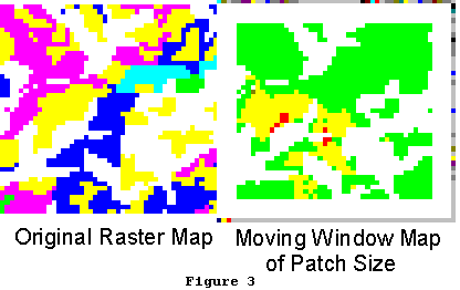
2.3.1.4. Moving window:
Using this procedure a rectangular "window" or single sampling area is moved systematically across the map to produce a new map (Fig. 2, 3). This sampling procedure can only be used with the measures that produce a single value or with a single class or group when measures produce distributions of values (Table 1). The first class or group specified when defining class or group limits (section 2.3.2.) is used if distributional measures are chosen with the moving window sampling method. In this case, the user should manually edit the r.le.para/recl_tb file so that the desired group is listed as the first group in this file.
Sampling begins with the upper left corner of the moving window placed over the upper
left corner of the sampling frame. It is strongly recommended that the user read the section on
 the GRASS mask (section
2.2.2) prior to setting up the
moving window, as this
mask can be used to speed
up the moving window
operation. The value of the
chosen measure is
calculated for the window
area. This value is
assigned to the location on
the new map layer
corresponding to the center
pixel in the window if the
window has odd (e.g. 3 X 3)
dimensions. The value is
assigned to the location on
the new map layer corresponding to the first pixel below and to the right of the center if the
window has even dimensions (e.g 6 X 10). If this pixel has the value "0," which means "no
data" in GRASS, then this pixel is skipped and a value of "0" is assigned to the corresponding
location in the new map. The window is then moved to the right (across the row) by one pixel,
and the process is repeated. At the end of the row, the window is moved down one pixel, and
then back across the row. This option produces a new map layer, whose dimensions are
smaller by approximately (m-1)/2 rows and columns, where m is the number of rows or columns
in the window.
the GRASS mask (section
2.2.2) prior to setting up the
moving window, as this
mask can be used to speed
up the moving window
operation. The value of the
chosen measure is
calculated for the window
area. This value is
assigned to the location on
the new map layer
corresponding to the center
pixel in the window if the
window has odd (e.g. 3 X 3)
dimensions. The value is
assigned to the location on
the new map layer corresponding to the first pixel below and to the right of the center if the
window has even dimensions (e.g 6 X 10). If this pixel has the value "0," which means "no
data" in GRASS, then this pixel is skipped and a value of "0" is assigned to the corresponding
location in the new map. The window is then moved to the right (across the row) by one pixel,
and the process is repeated. At the end of the row, the window is moved down one pixel, and
then back across the row. This option produces a new map layer, whose dimensions are
smaller by approximately (m-1)/2 rows and columns, where m is the number of rows or columns
in the window.
If the "Setup a moving window" option in the main menu is selected, first the program checks for an existing "move_wind" file, in the r.le.para subdirectory, containing moving window specifications from a previous session. The user is given the option to avoid overwriting this file by entering a new file name for the old "move_wind" file. The user is then prompted to choose between the following:
Use keyboard to enter moving window dimensions 1
Use the mouse to draw the moving window 2
If you choose 1, you will next be asked whether you want to use a rectangle or a circle, then to enter the shape and size (rectangle) or radius (circle). If you choose 2, then the functions of the three mouse buttons are displayed. The moving window is defined in the same way as a sampling unit. Once defined, it will be displayed in the upper left corner of the sampling frame, not where you drew it.
Users should be aware that moving window analyses are very slow, because a large number of sampling units are, in effect, used. See the appendix on "Time needed to complete analyses with the r.le programs" for some ideas about how moving window size and sampling frame area affect the needed time to complete the analyses.
2.3.2. Group/class limits
The r.le programs r.le.dist and r.le.patch allow the attribute categories in the input map to be reclassed into several attribute groups, and can then report the analysis results by each of these attribute groups. It is necessary to setup group limits for all measures that say "by gp" when typing "r.le.dist help" or "r.le.patch help" at the GRASS prompt. The same reclassing can be done with the measurement indices (e.g., size), except that each "bin" (class) of the reclassed indices is called an index class instead of a group. It is also necessary to setup class limits for all measures that say "by class" when typing "r.le.dist help" or "r.le.patch help" at the GRASS prompt.
Group/class limits are setup by choosing "Setup group or class limits" from the main menu upon starting r.le.setup, or you can create the files manually using a text editor. The program checks for existing group/class limit files in subdirectory r.le.para and allows the user to rename these files prior to continuing. If the files are not renamed the program will overwrite them. The files are named recl_tb (attribute group limits), size (size class limits), shape_PA (shape index class limits for perimeter/area index), shape_CPA (shape index class limits for corrected perimeter/area index), shape_RCC (shape index class limits for related circumscribing circle index), and from_to (for the r.le.dist program distance methods m7-m9). If you want to create these files manually, rather than using r.le.setup, refer to the appendix on "r.le.setup file formats."
Attribute groups and index classes are defined in different ways. In the r.le programs attribute groups are defined as in the following example:
1, 3, 5, 7, 9 thru 21 = 1 (comment)
31 thru 50 = 2 (comment)
end
In this example, the existing categories 1, 3, 5, 7, {9, 10, ... 20, 21} are included in the new group 1, while {31, 32, 33, ..., 49, 50} are included in the new group 2. The characters in bold are the "key words" that are required in the definition. Each line is called one "reclass rule." You can include a comment in parentheses.
When using r.le.dist with methods di1=m7, m8, or m9 you must first setup a "from_to" file in the r.le.para subdirectory. This file contains the number of the attribute group to measure from and the number of the attribute group to measure to. The "from_to" file can be setup using r.le.setup under the "Setup group or class limits" option in the main menu. After selecting this option, put an "x" in front of "From and To groups for di1=m7, m8, or m9" and follow the directions. The "from" and "to" groups are defined in a slightly different way, as in the following example:
1, 3, 5, 7, 9 thru 21 end (comment)
Here, the key word "end" is at the end of the line instead of in a new line. This rule is only used in the definition of the "from" and "to" attribute groups, because in this case both groups have one and only one reclass rule.
The GRASS reclass convention is adopted here with a little modification (see "r.reclass" command in the GRASS User's Manual). The difference is that r.le only allows one rule for each group while the GRASS r.reclass command allows more than one. The definition of "from" and "to" groups is simply the extension of the GRASS reclass rule. The advantage of using the GRASS reclass convention is that the user can generate a permanent reclassed map, using the GRASS r.reclass and r.resample programs, directly from the r.le setup files mentioned above.
The r.le measurement index classes are defined by the lower limits of the classes, as in the following example:
0.0, 10.0, 50.0, 200.0, -999
This means:
if v >= 0.0 and v < 10.0 then v belongs to index class 1;
if v >= 10.0 and v < 50.0 then v belongs to index class 2;
if v >= 50.0 and v < 200.0 then v belongs to index class 3;
if v >= 200.0 then v belongs to index class 4;
where v is the calculated index value and -999 marks the end of the index class definition. The measurement index can be the size index, one of the three shape indices, or one of the three distance indices.
The program is currently designed to allow no more than 25 attribute groups, 25 size classes, 25 shape index classes, and 25 distance index classes. As an alternative, the user may want to permanently group certain attributes prior to entering the r.le programs. For example, the user may want to group attributes 1-10, in a map whose attributes are ages, into a single attribute representing young patches. The user can do this using the GRASS r.reclass and r.resample commands, which will create a new map layer that can then be analyzed directly (without setting up group limits) with the r.le programs.
Of you want to calculate indices for each of the existing attributes in a raster map, you still need to setup group and class limits. However, in this case the groups would be defined to be identical to the attributes, as in the following example where there are only 3 attributes in the raster map:
1 = 1
2 = 2
3 = 3
end
This will allow "by gp" measures to output index values for attribute 1, 2, and 3 separately.
2.3.3. Color table
The user may want to change the color table for the map in the GRASS monitor window to make the sampling areas, cursor, and rubber band more visible. There are several different color tables that can be tried until a suitable one is found. Note that if you choose one of the other color tables from the menu, the color table for that GRASS raster map gets changed. To change it back to what it was originally, select "Set original color table" from the color table menu.
If the "Change the raster map color table" option in the main menu is selected, a menu titled "SELECT NEW COLOR TABLE FOR RASTER MAP" is displayed that has the following options:
"Aspect": generate a color table for aspect data.
"Color ramp": generate a color table with 3 sections: red only, green only, and blue only, each increasing from none to full intensity. This table is good for continuous data such as ages.
"Color wave": generate a color table with 3 sections: red only, green only, and blue only, each increasing from none to full intensity and back down to none. This table is good for continuous data like ages.
"Linear grey scale": generate a grey scale color table. Each color is a level of grey, increasing from black to white.
"Rainbow colors": generate a color table based on rainbow colors. the table generated here uses yellow, blue, indigo, violet, red. This table is good for continuous data such as ages.
"Random colors": generate random colors. Good as a first pass at a color table for nominal data. This option generates different color combinations for the color table each time. Therefore it can be used repeatedly until the satisfactory colors are displayed.
"Red-Yellow-Green sequence": generate a color table similar to that of "RAINBOW", except that the table starts at red, passes through yellow, and ends with green.
"Green-Yellow-Red sequence": generate a color table similar to that of "RAINBOW", except that the table starts at green, passes through yellow, and ends with red.
"Set original color table": assign the original color table to the input cell map if none of the above options improves the display during setup.
"Return to setup options menu"
After one of these options is selected, the menu titled "CHOOSE NEXT OPTION" is displayed that has the following options:
Don't save color table just chosen:
Return to color table menu 1
Return to setup option menu 2
Exit r.le.setup 3
Do save color table just chosen:
Return to setup options menu 4
Exit r.le.setup 5
Which number?
2.4. Syntax for the r.le analysis programs
The r.le analysis programs include r.le.dist, r.le.patch, and r.le.pixel. These programs are designed to do landscape ecological analyses by computing the spatial measures selected from the measure list available with each program. Each program will be explained in the following sections. All three r.le analysis programs can be started at the GRASS prompt (>) using either a command-line or interactive method. To invoke the command-line help menu, type the name of the program, a space, and the word "help" (e.g. r.le.pixel help).
The interactive version of each program is invoked by simply typing the command followed by a carriage return. The GRASS parsing routine will then ask the user to answer questions and specify parameter values. The possible parameter values are listed along with a brief summary of their meanings.
The command-line version of each program is invoked by typing the name of the program, followed by a list of parameters and parameter values, on the command line, followed by a carriage return. Each command-line parameter is described briefly in help menus for each of the programs.
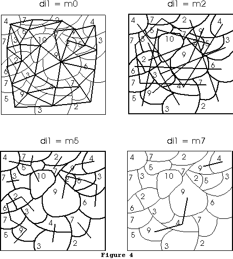
An example of command syntax, which was used to produce the core area map (Fig. 4) is:
r.le.patch map=t.no0 co1=2 co2=c1 -c
2.5. The r.le.dist program
The r.le.dist program can be used to measure distances between patches and report those distances using several methods. See section 2.4. for an explanation of how to start the r.le.dist program.
2.5.1. Syntax for the r.le.dist program
The syntax for the command-line version and the parameters for both interactive and command-line versions are as follows:
r.le.dist [-bntu] map=name [sam=name] [reg=name] [ski=value] [can=value] [di1=name[,name,...]] [di2=value[,...]] [out=name]
where:
brackets [] indicate optional parameters or values
-n is a flag to request an output map showing the patch number. This number is the number assigned sequentially as the program traces the patches. It is also the number that is displayed in the individual patch measure output file specified with the "out" parameter.
-t is a flag to request 4 neighbor tracing instead of the default 8 neighbor tracing. 4 neighbor tracing adds a pixel to a patch only if it is in the same row or column as the current pixel while tracing proceeds. 8 neighbor tracing adds pixels to a patch if they are among the surrounding 8 neighboring pixels.
-u is a flag to request output maps showing the sampling units that were setup for each scale using r.le.setup.
map is the GRASS raster map to be analyzed. This raster map must be available in the user's working GRASS database (/location/mapset/),
sam is the kind of sampling area: w, u, m, or r, where w=whole map, u=sampling units, m=moving window, or r=regions.
reg is the name of the regions map to be used when sam=r,
ski is to specify whether to skip some points when searching along the patch boundary. This is used to speed up the distance calculations.
ski <= 0 means don't skip;
ski > 0 means:
if np > ski + 50 - search every other boundary point;
if np > ski + 200 - search every third boundary point;
if np > ski + 500 - search every fourth boundary point;
if np > ski + 2000 - search every fifth boundary point;
where np is the number of total boundary pixels of a patch. This is effective with the center-edge and edge-edge distance measures. Default is ski = 0, and maximum value is 10.
can is the maximum number of candidate patches on the nearest-neighbor-list when searching for the nearest neighbor patch. It means when searching for the nearest patch of a particular patch, find can "close" patches first using a simple method, then find out the nearest patch from these can candidate patches with point-by-point calculation. The legal range of can is 1-30. If can < 1, can = 1; if can > 30, can = 30. The default value is can = 30.
di1 is the distance method. Distance can be measured and summarized in a variety of ways: (1) from each patch in the sampling area or only from patches belonging to a specific attribute group (gp), (2) to all adjacent neighboring patches or only to the single nearest neighbor patch, (3) regardless of the group of the neighbor or only to patches belonging to a specific group, (4) from center to center, from center to edge, or from edge to edge. See the explanation below about how these distances are calculated. There are nine combinations of these that represent choices for di2 (some examples are illustrated in Fig. 4):
From each patch in the sampling area
to all the adjacent neighbors of the patch
m0 = Distance is center-center
m1 = Distance is center-edge
to the nearest patch of the same gp
m2 = Distance is center-center
m3 = Distance is center-edge
m4 = Distance is edge-edge
to the nearest patch of any different gp
m5 = Distance is center-center
m6 = Distance is center-edge
From each patch of a specific gp
to the nearest patch of a specific gp
m7 = Distance is center-center
m8 = Distance is center-edge
m9 = Distance is edge-edge
In the case of m7 to m9, you must first have set up a "from_to" file in the r.le.para subdirectory, before you can run this option. See section 2.3.2.
 A polygon is considered to be adjacent to another polygon if it
shares either an edge or a single vertex with the polygon. Polygon center
x and y coordinates
are defined as the
sum of the x and y
coordinates of all the
boundary points
divided by the
number of points.
This value is
rounded, so that the
center is the row and
column value of the
pixel containing the
center. Note that
with this algorithm the
center can be outside
the patch if the patch
is irregularly shaped.
All distances are
Euclidean distances
in pixels. Distance
from center to center
is the distance from
the center of the
center pixel of one
polygon to the center
of the center pixel of
another polygon.
Thus two pixels next
to each other in a row
are a distance of 1.0
apart, while two
pixels next to each
other on a diagonal are 1.414 apart. Distance from center to edge is
measured from the center of the center pixel of one polygon to the edge
of the closest pixel on the boundary of the other polygon. Thus 2 pixels
next to each other in a row are distance 0.5 apart, based on center to
edge distance. Distance from edge to edge is measured as the minimum
distance between the edges of any pixels on the boundary of the two
polygons. Thus two pixels next to each other on a row or a diagonal are a
distance 0.0 apart. Note that with methods m0-m1 a very large number
of distances are calculated, whereas with methods m2-m6 the number of
distances measured is the same as the number of patches in the
sampling area. With methods m7-m9 the number of distances is the
same as the number of patches in the sampling area that belong to the
"from" group. Note that the distance between polygons A and B may be
used more than once with any of the measures, as this distance may be
calculated once with polygon A as the "from" polygon and once with
polygon B as the "from" polygon. The distance between polygons A and
B is the same no matter which is the "from" polygon if center-center or
edge-edge distance are calculated, but it is not the same if center-edge
distance is calculated.
A polygon is considered to be adjacent to another polygon if it
shares either an edge or a single vertex with the polygon. Polygon center
x and y coordinates
are defined as the
sum of the x and y
coordinates of all the
boundary points
divided by the
number of points.
This value is
rounded, so that the
center is the row and
column value of the
pixel containing the
center. Note that
with this algorithm the
center can be outside
the patch if the patch
is irregularly shaped.
All distances are
Euclidean distances
in pixels. Distance
from center to center
is the distance from
the center of the
center pixel of one
polygon to the center
of the center pixel of
another polygon.
Thus two pixels next
to each other in a row
are a distance of 1.0
apart, while two
pixels next to each
other on a diagonal are 1.414 apart. Distance from center to edge is
measured from the center of the center pixel of one polygon to the edge
of the closest pixel on the boundary of the other polygon. Thus 2 pixels
next to each other in a row are distance 0.5 apart, based on center to
edge distance. Distance from edge to edge is measured as the minimum
distance between the edges of any pixels on the boundary of the two
polygons. Thus two pixels next to each other on a row or a diagonal are a
distance 0.0 apart. Note that with methods m0-m1 a very large number
of distances are calculated, whereas with methods m2-m6 the number of
distances measured is the same as the number of patches in the
sampling area. With methods m7-m9 the number of distances is the
same as the number of patches in the sampling area that belong to the
"from" group. Note that the distance between polygons A and B may be
used more than once with any of the measures, as this distance may be
calculated once with polygon A as the "from" polygon and once with
polygon B as the "from" polygon. The distance between polygons A and
B is the same no matter which is the "from" polygon if center-center or
edge-edge distance are calculated, but it is not the same if center-edge
distance is calculated.
di2 is the distance measure, which can have these values:
n1 = Mean distance: This is simply the total of all the distances divided by the number of distances measured. Note that when a patch does not have an adjacent or nearest neighbor that patch is omitted from the calculation of the mean. Its distance is not recorded as zero.
n2 = Standard deviation of distance: This is the standard deviation of the distances in the sampling area. It is calculated as:
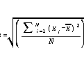
where xi is distance i, x is the mean distance of all the distances, and N is the number of distances. Note that when a patch does not have an adjacent or nearest neighbor that patch is omitted from the calculation of the standard deviation. Its distance is not recorded as zero.
n3 = Mean distance by group: This is the mean distance within the sampling area, as in M, but calculated separately for the patches within each group.
n4 = Standard deviation distance by group: This is the standard deviation of distances with the sampling area, as in n2, but calculated separately for the patches within each group.
n5 = Number of distances by distance class: This is a tally of the number of distances within each of up to 25 user-specified distance classes.
n6 = Number of distances by distance class by group: This is a tally of the number of distances within each of up to 25 user-specified distance classes, as in n5, but calculated separately for the patches within each group.
out is the name of the output file containing a table listing distance measures for each patch. Obtain this table by specifying a filename (e.g., out=table) for a file that will be written in the r.le.out subdirectory. If out=head is specified, then the file will contain a line with column headings at the top of the file. See section 2.8.2 for the format of the output file. Note that when no adjacent or nearest neighbors are found for a particular patch there will be no entry for that patch in this output file.
2.5.2. Examples of the use of the r.le.dist program
EXAMPLE 1: Measure the nearest neighbor distance from a patch in group 1 to another patch in group 1 in raster map "example1" using center-to-center distances, output the individual measurements for each patch into file "head" and calculate the mean and standard deviation of these measurements. To do this you would first use r.le.setup to setup a "from_to" file in the r.le.para subdirectory specifying which attributes belong in group 1. Assuming you are willing to accept the default values for parameters, then type:
r.le.dist map=example1 di1=m7 di2=n1,n2 out=head
The file "r.le.out/head" will contain a list of patches and the corresponding distances from each patch. The file "r.le.out/n1-2.out" will contain a single line with the mean distance and the standard deviation of distance.
EXAMPLE 2: Measure the distance from each patch to all its adjacent neighbors and do this for every patch in raster map "example2" using center-to-edge distances. Report the number of these distances that are in the following distance classes: 0-5 pixels, 6-10 pixels, > 10 pixels. To do this you would first use r.le.setup to setup a "dist_ce" file, which will contain the following entry:
0.00 6.00 11.00 -999 - lower limits.
This entry indicates the lower limit for each distance class, and -999 to indicate the end of the list. Once this file is setup, assuming that you accept the default values for parameters, then you can complete the calculation by typing:
r.le.dist map=example2 di1=m1 di2=n5
EXAMPLE 3: Use a 5 cell X 5 cell moving window to create a new map from raster map "example3" to show the mean distance, for all pixels within group 1, to the nearest neighboring patch in group 2, based on edge-to-edge distances. To speed up the calculations, skip every other pixel in the boundary when finding distances, and only use 10 candidate patches. To do this, first use r.le.setup to make a "from_to" file specifying the attributes that belong in group 1 and the attributes that belong in group 2. Then use r.le.setup to setup the moving window. Choose the option in r.le.setup that allows you to use the keyboard to setup the moving window, then enter 5 5 to choose a 5 by 5 moving window. Then to complete the calculation and make the new map type:
r.le.dist map=example3 sam=m ski=1 can=10 di1=m9 di2=n1
The program will show a decreasing number of windows as they are completed and the estimated time of completion. Once the program is completed, a new map called "n1" will be created. Use "g.list rast" to see that map "n1" is there. Display the map in a monitor window by typing "d.rast n1".
2.6. The r.le.patch program
This program can be used to calculate attribute, patch size, core (interior) size, shape, fractal dimension, and perimeter measures for sets of patches in a landscape. See section 2.4. for an explanation of how to start the r.le.patch program.
2.6.1. Syntax for the r.le.patch program
The syntax for the command-line version and the parameters for both interactive and command-line versions are as follows:
r.le.patch [-bcnptu] map=name [sam=name] [reg=name] [att=name[,name,...]]
[siz=name[,name,...]] [co1=value] [co2=name[,name,...]] [sh1=name]
[sh2=name[,name,...]] [fra=name] [per=name[,name,...]] [out=name]
where:
brackets [] indicate optional parameters or values
-c is a flag o request an output map called "interior" which will contain patch interiors.
-n is a flag to request an output map showing the patch number. This number is the number assigned sequentially as the program traces the patches. It is also the number that is displayed in the individual patch measure output file specified with the "out" parameter.
-p is a flag to request that the sampling area boundary be counted as though it were perimeter for patches adjoining the boundary.
-t is a flag to request 4 neighbor tracing instead of the default 8 neighbor tracing. 4 neighbor tracing adds a pixel to a patch only if it is in the same row or column as the current pixel while tracing proceeds. 8 neighbor tracing adds pixels to a patch if they are among the surrounding 8 neighboring pixels.
-u is a flag to request output maps showing the sampling units that were setup for each scale using r.le.setup
map is the GRASS raster map to be analyzed. This raster map must be available in the user's working GRASS database (/location/mapset/),
sam is the kind of sampling area: w, u, m, or r, where w=whole map, u=sampling units, m=moving window, or r=regions.
reg is the name of the regions map to be used when sam=r,
att is a set of attribute measures:
a1 = Mean pixel attribute: This is the average value of the attributes of all the pixels in the sampling area. Each attribute is weighted by how many pixels it occupies. The mean pixel attribute, x, is then:
a2 = Standard deviation of pixel attribute: This is simply the standard deviation of the attributes of the pixels in the sampling area. The standard deviation of pixel attributes, s, is then:
a3 = Mean patch attribute: This is the average attribute of all the patches in the sampling area. It is calculated by summing up the attributes of each patch and dividing by the number of patches.
a4 = Standard deviation of patch attributes: This is simply the standard deviation of the attributes of the patches in the sampling area. The standard deviation of patch attributes, s, is then:
a5 = Cover by group: This is a measure of the amount of land area covered by each group. Cover is expressed as the decimal fraction of the sampling area occupied by each group.
a6 = Density by group: This is a measure of the number of patches in each group. It is expressed as the raw number of patches that are in each group.
a7 = Total density: This is a measure of the raw total number of patches in the sampling area.
siz is a set of size measures:
s1 = Mean patch size: This measure, the mean size or area (in pixels) of the patches in the sampling area, is calculated for all patches in the sampling area, ignoring the group of each patch, by simply dividing the sampling area size by the number of patches.
s2 = Standard deviation of patch size: This is the standard deviation of the sizes (in pixels) of all the patches in the sampling area, ignoring the group of each patch. The standard deviation of patch size, s, is then:
s3 = Mean patch size by group: This is the mean patch size within the sampling area, as in s1, but calculated separately for all the patches within each group.
s4 = Standard deviation of patch size by group: This is the standard deviation of the sizes (in pixels) of all the patches in the sampling area, as in s2, but calculated separately for all the patches within each group.
s5 = Number by size class: This is a measure of the number of patches in the sampling area that fall within each size class. This measure is calculated for all the patches in the sampling area, ignoring the group of each patch. The results can be reported for up to 25 size classes.
s6 = Number by size class by group: This is a measure of the number of patches in the sampling area that fall within each size class. This measure is calculated separately for all the patches within each group. The results can be reported for up to 25 size classes.
co1 is the width of the edge in pixels for use with co2. This represents how wide the area of the patch is that is suspected to be affected by the patch edge.
co2 is a set of core size measures. This represents the size of the patch core after the edge width specified by co1 has been removed from the outside of the patch. A map of the core or "interior" area can be obtained by specifying the -c flag.
c1 = Mean core size: This measure, the mean size or area (in pixels) of the core of patches in the sampling area, is calculated for all patches in the sampling area, ignoring the group of each patch.
c2 = Standard deviation of core size: This is the standard deviation of the sizes (in pixels) of the cores of all the patches in the sampling area, ignoring the group of each patch. The standard deviation of core size, s, is then:
c3 = Mean edge size: This measure, the mean size or area (in pixels) of the edge of patches in the sampling area, is calculated for all patches in the sampling area, ignoring the group of each patch.
c4 = Standard deviation of edge size: This is the standard deviation of the sizes (in pixels) of the edges of all the patches in the sampling area, ignoring the group of each patch. The standard deviation of edge size, s, is then:
c5 = Mean core size by group: This is the mean core size within the sampling area, as in c1, but calculated separately for all the patches within each group.
c6 = Standard deviation of core size by group: This is the standard deviation of the sizes (in pixels) of the cores all the patches in the sampling area, as in c2, but calculated separately for all the patches within each group.
c7 = Mean edge size by group: This is the mean edge size within the sampling area, as in c3, but calculated separately for all the patches within each group.
c8 = Standard deviation of edge size by group: This is the standard deviation of the sizes (in pixels) of the edges all the patches in the sampling area, as in c4, but calculated separately for all the patches within each group.
c9 = Number by size class: This is a measure of the number of patches in the sampling area that fall within each core size class. This measure is calculated for all the patches in the sampling area, ignoring the group of each patch. The results can be reported for up to 25 size classes.
c10 = Number by size class by group: This is a measure of the number of patches in the sampling area that fall within each core size class. This measure is calculated separately for all the patches within each group. The results can be reported for up to 25 size classes.
sh1 is a set of shape indices. There are three possible indices of patch shape here. These are only three of the simplest indices of two-dimensional shape (Austin 1984; MacEachren 1985):
m1 = Perimeter/area: The total length of the perimeter of each patch is divided by its area, and the mean of these values is then calculated. Where patches extend outside of the sampling area, the sampling area edge is considered to be the edge of the patch. A problem with the ratio of perimeter/area as a shape index is that it varies with the size of the patch.
m2 = Corrected perimeter/area: The formula for this index for each patch is: (0.282 X perimeter)/(area)1/2. The mean of these values for all the patches is then calculated. This index corrects for the size problem of index E. The index varies from a value of 0.0 for a circle to infinity for an infinitely long and narrow shape. It is 1.12 for a square.
m3 = Related circumscribing circle: This index compares the area of the patch to the area of the smallest circle that can circumscribe the patch. The formula for each patch is:
sh2 is a set of shape measures:
h1 = Mean patch shape: This measure is calculated for all patches in the sampling area, ignoring the group of each patch. The mean patch shape is simply the sum of the patch shape indices for every patch divided by the number of patches.
h2 = Standard deviation of patch shape: This is the standard deviation of the shapes of all the patches in the sampling area, ignoring the group of each patch. The standard deviation of patch shape, s, is then:
h3 = Mean patch shape by group: This is the mean patch shape within the sampling area, as in h1, but calculated separately for all the patches within each group.
h4 = Standard deviation of patch shape by group: This is the standard deviation of the shapes of all the patches in the sampling area, as in h2, but calculated separately for all the patches within each group.
h5 = Number by shape index class: This is the number of patches, in the sampling area, whose shape index value falls within each shape index class. This measure is calculated for all the patches in the sampling area, ignoring the group of each patch. The results can be reported for up to 25 shape index classes.
h6 = Number by shape index class by group: This is the number of patches, in the sampling area, whose shape index value falls within each shape index class. This measure is calculated separately for all the patches in each group. The results can be reported for up to 25 shape index classes.
fra is the fractal dimension, D, for the patches in a sampling area, and is a measure of the complexity of the perimeter. The current version implements only the perimeter-area interpretation of fractal dimension (Krummel et al. 1987). The formula for fractal dimension, d, is:
f1 = perimeter-area fractal dimension
per is the perimeter of a patch, which is the total length of external and internal boundary expressed as the number of pixel edges. The perimeter includes the edge of the sampling area when the -p flag is specified, but the default excludes the sampling area edge. The perimeter is measured for each patch individually. Thus boundaries between adjoining patches get measured twice, once for each patch. The edge measures of r.le.pixel do not measure shared boundaries twice. There are several possible measures of perimeter:
p1 = Sum of the perimeters: This is the total of all the perimeters for all the patches in the sampling area, ignoring the group to which the patch belongs.
p2 = Mean perimeter: This is the mean perimeter length for the patches in the sampling area, ignoring the group to which the patches belong. It is calculated by dividing the sum of the perimeters by the number of patches.
p3 = Standard deviation of perimeter: This is the standard deviation of perimeter length for all the patches in the sampling area, ignoring the group to which they belong. The standard deviation of perimeter length, s, is then:
p4 = Sum of the perimeters by group: This is the total of all the perimeters for all the patches in the sampling area, as in p1, calculated separately for the patches belonging to each group.
p5 = Mean perimeter by group: This is the mean perimeter length for the patches in the sampling area, calculated separately for the patches belonging to each group. It is calculated by dividing the sum of the perimeters by the number of patches within each group.
p6 = Standard deviation of perimeter by group: This is the standard deviation of perimeter length for all the patches in the sampling area, as in p3, but calculated separately for the patches belonging to each group.
out is the name of the output file containing a table listing individual measures for each patch (e.g., size, shape). Obtain this table by specifying a filename (e.g., out=table) for a file that will be written in the r.le.out subdirectory. If out=head is specified, then the file will contain a line with column headings at the top of the file. See section 2.8.2 for the format of the output file.
2.6.2. Examples of the use of the r.le.patch program
EXAMPLE 1: Measure and report mean patch size and mean perimeter for all patches in raster map "example1" and report patch size and perimeter for each patch. Make a new map with each pixel attribute the number of the patch; this number corresponds to the number in the resulting "r.le.out/head" file. Do not count the sampling area boundary as perimeter and use 8 neighbor tracing. To do this simply type:
r.le.patch map=example1 -n siz=s1 per=p2 out=head
Since the default is to not count sampling area boundary as perimeter and to use 8 neighbor tracing, nothing need be typed for these options. The mean patch size value will be found in file "r.le.out/s1-2.out" and the mean perimeter value in file "r.le.out/p1-3.out". You will find a list of each patch's size and perimeter in file "r.le.out/head" and a new map called "num" should be found in your mapset. Use "g.list rast" to see if it's there and "d.rast num" to display it.
EXAMPLE 2: Measure and report the mean size of patch core areas for all forest areas in map "example2" given that the edge of patches extends into the patch 2 pixels. Make a new map showing the core areas of each patch, and report the amount of core area for each individual patch. To do this first use r.le.setup and click on "GROUP/CLASS LIMITS" at the main menu. Then put an "x" where there's now a dash under "r.le.patch - Attribute groups"; then input a list of the attributes that belong in the group "forest" which can be given a group number of "1". Now to complete the analysis type:
r.le.patch map=example2 -c co1=2 co2=c1 out=head
Because you specified the -c flag, a new map called "interior" will be produced in your mapset. An example of this map is in Fig. 4, which was produced with the command above. This map will be like the original map except that a 2 pixel margin around each patch will be reclassified to category 0. Some patches, as a result, may disappear if they were only a few pixels wide. Since you specified "out=head" you can look at file "r.le.out/head" to see a list of each patch in the map and its core area. Look at file "r.le.out/c1-4.out" file to see the mean size of core areas.
EXAMPLE 3: Setup a random nonoverlapping sampling network of 25 sampling units each 10 pixels wide by 5 pixels high, and place this network over the part of raster map "example3" that is in Albany County. Do the same thing in adjoining Carbon County. The purpose of this example is to see whether landscapes in Albany County are more variable than are those in Carbon County. In each sampling unit measure the sum of perimeters. To do this first make a raster map (or use an existing map?) showing Albany and Carbon counties. You can use v.digit or some other approach to make this map. Once the map is made, type "r.mask" and put a "1" in front of the attribute representing Albany County. What this does is it masks Albany County so all attributes in this county show through, while those areas outside Albany County do not. Subsequent use of r.le.patch is thus restricted to the Albany County area. Next, start r.le.setup, click on "SAMPLING UNITS" at the main menu, then enter "1" to use the keyboard to enter sampling unit parameters. Then type "1" to select just one scale. Then type "1" to select the random nonoverlapping method of sampling unit distribution. When asked about sampling unit shape, enter 2.0 to get a shape that is twice as wide as high (we need 10 pixels wide by 5 pixels high). Then enter "50" to get a sampling unit that is the right size (10 X 5 = 50). Finally, enter "25" as the number of sampling units. The sampling units will be displayed on the screen as they are placed. Answer "y" to accept the set of sampling units. Enter "n" to avoid refreshing the screen. Then click on "EXIT-SAVE" at the main menu. The sampling unit file is saved as file "r.le.para/units" You can check to see that the file was made correctly by typing "more r.le.para/units" and the file contents will display on screen. By the way, the sampling unit framework you just setup should look something like the one in Fig. 1, which was made using the above procedure. Now, you are ready to run the r.le.patch analysis using the sampling unit network you just setup. To complete the analysis just type:
r.le.patch map=example3 sam=u per=p1
The "sam=u" parameter requests that the sampling unit network be used. After the program is completed, type "more r.le.out/p1-3.out" to see the result. This file will contain 25 lines listing the sum of perimeters for each of the sampling units.
2.7. The r.le.pixel program
The r.le.pixel program contains a set of measures for attributes, diversity, texture, juxtaposition, and edge. See section 2.4. for an explanation of how to start the r.le.pixel program.
2.7.1. Syntax for the r.le.pixel program
The syntax for the command-line version and the parameters for both interactive and command-line versions are as follows:
r.le.pixel [-beuz] map=name [sam=nam] [reg=name] [att=name[,name,...]]
[div=name[,name,...]] [te1=name] [te2=name[,name,...]]
[jux=name[,name,...]] [edg=name[,name,...]]
where:
brackets [] indicate optional parameters or values
-e is a flag to request an output map showing the location of edges of a particular type as specified in file r.le.para/edge
-u is a flag to request output maps showing the sampling units that were setup for each scale using r.le.setup
-z is a flag to request an output map 'zscores' with standardized scores. These scores rescale the attribute scores so they are subtracted from the mean attribute and divided by the standard deviation. They are expressed as integers by multiplying by 100.
map is the GRASS raster map to be analyzed. This raster map must be available in the user's working GRASS database (/location/mapset/),
sam is the kind of sampling area: w, u, m, or r, where w=whole map, u=sampling units, m=moving window, or r=regions,
reg is the name of the regions map to be used when sam=r,
div is a set of measures of the diversity of patch attributes within the sampling area. The relative merits of the following measures have been evaluated by Peet (1974):
d1 = Richness: This is simply the number of different patch attributes present in the sampling area.
d2 = Shannon index (H'): This is an index that combines richness and evenness. Its formula is:
d3 = Dominance: This index is related to the Shannon index, but emphasizes the deviation from evenness. The formula for dominance, D, is:
d4 = Inverse Simpson's index (1/S): This index also combines richness and evenness. It is a measure of the probability of encountering two pixels of the same attribute when taking a random sample of two pixels. Its formula is:
te1 is a set of seven methods for analyzing adjacencies for each pixel (Fig. 5):
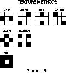 m1 = 2N-H
m2 = 2N-45
m3 = 2N-V
m4 = 2N-135
m5 = 4N-HV
m6 = 4N-DIAG
m7 = 8N
te2 is a set of texture measures that quantify the adjacency of similar attributes. They are in a sense simply local (neighborhood) measures of diversity. Most of the measures have been reviewed by Haralick et al. (1973), Haralick (1975), and Musick and Glover (1990). All of the measures require calculation of a grey-level co-occurrence matrix (GLCM), which is m X m, where m is the number of attributes in the sampling area. The GLCM matrix contains entries, Pij, which are the total number of times that attribute i is adjacent to attribute j. The total number of adjacencies is calculated by moving through the sampling area pixel-by-pixel. There are five measures of texture that can be calculated:
t1 = Contagion: This measure quantifies the degree of clumping, and is a modification of the entropy measure (N). The formula for contagion, C, is:
t2 = Angular second moment: This is a measure of the homogeneity of the landscape. Larger values indicate more homogeneity. The formula for angular second moment, ASM, is:
t3 = Inverse difference moment: The formula for inverse difference moment, IDM, is:
In calculating juxtaposition, diagonal neighbors get a quantity ranking, q, of 1.0, while horizontal and vertical neighbors get a quantity ranking of 2.0 because horizontal and vertical edges share more edge than do diagonal edges in a raster representation of patches.
Weights, wij, are assigned by the user to edges between different attributes. A weighting matrix, which is m X m, where m is the number of different attributes, must be created with an editor and stored as an ASCII file named "weight" in the r.le.para subdirectory. The weighting matrix has the format:
att1 att2 ... attm
att1 w11 wi2 ... w1m
att2 w21 w22 ... w2m
... ... ... ... ...
attm wm1 wm2 ... wmm
where atti is attribute i, expressed as an integer, of m attributes, and wij is the weight, expressed as a real number between -1.0 and +1.0, assigned when attribute i and attribute j share an edge. Example of a weight file:
1 2 3 4
1 0.5 0.3 0.2 0.6
2 0.3 0.1 0.4 0.7
3 0.2 0.4 0.0 0.4
4 0.6 0.7 0.4 0.1
The two juxtaposition measures, then, are:
j1 = Mean juxtaposition: The program first calculates the juxtaposition for each pixel in the map layer by examining edges with attributes in the 8 cells surrounding each pixel. Then the program finds the mean juxtaposition of all the cells in the sampling area, by summing all the juxtaposition values and dividing by the number of pixels.
j2 = Standard deviation of juxtaposition: This is the standard deviation for all the pixels in the sampling area. The standard deviation, s, is given by:
edg is the length of patch boundary, but in summing edge for all the patches in a sampling area edges are counted only once when they are shared between two patches. An "edge" is considered to occur only between adjoining cells along a row or within a column. Diagonal neighbors with different attributes are not considered edge.
e1 = Sum of the edges: This is the total length of all the edges, counted only once, of all the patches in the sampling area. It differs from the total perimeter length which sums the length of each patch's total perimeter, effectively counting shared perimeters twice.
e2 = Sum of edges by type: This is the length of all the edges of a particular type. The type of edge that is desired is specified by creating a file "r.le.para/edge" that has the following format:
att1 att2 ... attm
att1 e11 ei2 ... e1m
att2 e21 e22 ... e2m
... ... ... ... ...
attm em1 em2 ... emm
where atti is attribute i, expressed as an integer, of m attributes, and eij is a 1 if the edge between attribute i and j should be counted and 0 if it should not be counted. Here is an example of an edge file, which specifies that only edges between attributes 1 and 2 should be measured:
1 2 3
1 0 1 0
2 1 0 0
3 0 0 0
2.7.2. Examples of the use of the r.le.pixel program
EXAMPLE 1: Use a 3 pixel by 3 pixel moving window to produce a new map of the richness of pixel types in raster map "example1". First start r.le.setup and click on MOVING WINDOW at the main menu. Answer "n" to the question "Use mouse to define the moving window?" Then at the prompt "Enter COLUMNS & ROWS of the window" enter "3 3" to get a 3 x 3 moving window. Then answer "n" to not refresh the screen. Finally, click on EXIT-SAVE at the main menu to exit and save the moving window parameters in the "r.le.para/move_wind" file. You can look at this file by typing "more r.le.para/move_wind" to make sure the setup worked. Now, to complete the analysis type:
r.le.pixel map=example1 sam=m div=d1
The program will show the progress of moving windows and the expected completion time. When it is done, the program will produce a new map called "d1" in your current mapset. Use "g.list rast" to see if it is there and "d.rast d1" to display it. The map in Figure 3 was produced using the above procedure and analysis.
EXAMPLE 2: Measure the amount of edge between attributes 1 and 2 in raster map "example2" and produce a new map showing where these types of edges occur. Assume that the map has only 4 attributes. To do this, first use a text editor to make a file "r.le.para/edge" as follows:
1 2 3 4
1 0 1 0 0
2 1 0 0 0
3 0 0 0 0
4 0 0 0 0
This file has a "1" to indicate that edges between attributes 1 and 2 or between 2 and 1 should be counted. Now, to complete the analysis type:
r.le.pixel map=example2 -e edg=e2
The -e flag requests a new map of the edges between attributes 1 and 2. This new map will be created in your current mapset and it will be called "edge". You can see if the map is there by typing "g.list rast" and use "d.rast edge" to display it. The length of edge between attributes 1 and 2 will be reported in file "r.le.out/e2.out". You can look at this file by typing "more r.le.out/e2.out".
2.8. Output from the r.le analysis programs
2.8.1. Moving window output maps and their interpretation
All three of the r.le analysis programs produce a new raster map when the moving window method of sampling is used. The name of the output map is the same as the measure code you selected. For example, the following input:
r.le.pixel map=example sam=m div=d1,d3
will produce new moving window maps called "d1" and "d3" in your current mapset. You can request up to 25 moving window output maps simultaneously. GRASS will not allow more than 25 files to be open simultaneously.
GRASS allows raster maps to contain only integers, and this presents problems for analyses that produce real numbers as output (e.g., r.le.pixel's Shannon diversity measure). For this reason, the results of moving window analyses for most measures are multiplied by 1, 10, 100, or 1000 to produce multiplied integer representations of the actual real numbers that should be output. Table 2 contains a list of each of the measures and the multiplier used. At the present time, these multipliers are embedded in the source code. In the future, they will be stored in a file, that can be edited, in the r.le.para subdirectory.
All moving window output maps are assigned a green-yellow-red color table, which can be changed by the user with the GRASS r.colors command.
2.8.2. Output files and data formats from non-moving window analyses
Several output files are produced by the r.le programs. Output files are stored in the r.le.out subdirectory. The output files and their format are as follows (gp = attribute group):
From r.le.dist: All distances are given in units of pixels.
n1-2.out
Scale Sampl. area# Mean distance Standard deviation distance
n3.out
Scale Sampl. area# Mean distance by gp
n4.out
Scale Sampl. area# Standard deviation distance by gp
n5.out
Scale Sampl. area# Number of distances in ea. distance class
n6.out
Scale Sampl. area#
No. in ea. index class-gp 1
No. in ea. index class-gp 2
... ...
No. in ea. index class-gp n
From r.le.patch: Size and perimeter measures are given in pixels.
a1-4.out
Scale Sampl. area# Mn. pixel attrib. St. dev. pixel attrib. Mn. patch attrib. St. dev. patch attrib.
a5.out
Scale Sampl. area# Cover by gp as a fraction
a6.out
Scale Sampl. area# Density by gp as a raw number
a7.out
Scale Sampl. area# Total number of patches
s1-2.out
Scale Sampl. area# Mn. patch size St. dev. patch size
s3.out
Scale Sampl. area# Mean patch size-by gp
s4.out
Scale Sampl. area# St. dev. patch size by gp
s5.out
Scale Sampl. area# No. by patch size class
s6.out
Scale Sampl. area#
No. by patch size class-gp 1
No. by patch size class-gp 2
...
No. by patch size class-gp n
c1-4.out
Scale Sampl. area# Mn. core size St. dev. core size
Mn. edge size St. dev. edge size
c5.out
Scale Sampl. area# Mn. core size by gp
c6.out
Scale Sampl. area# St. dev. core size by gp
c7.out
Scale Sampl. area# Mn. edge size by gp
c8.out
Scale Sampl. area# St. dev. edge size by gp
c9c.out
Scale Sampl. area# No. by core size class
c9e.out
Scale Sampl. area# No. by edge size class
c10c.out
Scale Sampl. area#
No. by core size class-gp 1
No. by core size class-gp 2
...
No. by core size class-gp n
c10e.out
Scale Sampl. area#
No. by edge size class-gp 1
No. by edge size class-gp 2
...
No. by edge size class-gp n
h1-2.out
Scale Sampl. area# Mean shape St. dev. shape
h3.out
Scale Sampl. area# Mean shape-by gp
h4.out
Scale Sampl. area# Standard deviation shape-by gp
h5.out
Scale Sampl. area# No. by shape index class
h6.out
Scale Sampl. area#
No. in ea. index class-gp 1
No. in ea. index class-gp 2
... ...
No. in ea. index class-gp n
f1.out
Scale Sampl. area# Fractal dimension R2 SigB
p1-3.out
Scale Sampl. area# Sum of perim. Mean perim. Standard deviation perim.
p4.out
Scale Sampl. area# Sum of perim.-by gp
p5.out
Scale Sampl. area# Mean perim.-by gp
p6.out
Scale Sampl. area# Standard deviation perim.-by gp
From r.le.pixel: Sum of edges is given in pixels.
d1-4.out
Scale Sampl. area# Richness Shannon Domin. Inv. Simpson's
t1-5.out
Scale Sampl. area# Contagion ASM IDM ENT Contrast
j1-2.out
Scale Sampl. area# Mean jux. St. dev. jux.
e1.out
Scale Sampl. area# Sum of edges
e2.out
Scale Sampl. area# Sum of edges by type
Both the r.le.dist and r.le.patch programs can be used to produce an output file containing measures for individual patches when the "out=" parameter is specified. The file will be written into the r.le.out subdirectory. The files have the following formats:
a. from r.le.dist:
FM PATCH Center Edge TO PATCH Center Edge DIST-
scale unit num att row col row col num att row col row col ANCE
Note that for the Center and Edge columns only the appropriate columns will be filled with row and col values. For example, if you choose di1=m6 only the FM PATCH Center row and col and TO PATCH Edge row and col will have values, as M6 specifies from center to edge. The FM PATCH Edge and TO PATCH Center row and col will be filled with zeroes. Also note that if a patch does not have an adjacent or nearest neighbor (depending on the method chosen), there will be no entry for that patch in this table. If you specify out=head as the filename, then the output file will have the column headings listed above. If you specify another name for the output file, then it will lack the column headings.
b. from r.le.patch
scale unit num att row col area per long P/A CP/A RCC
If you specify out=head as the filename, then the output file will have the column headings listed above. They will be slightly different if you are measuring core areas. If you specify another name for the output file, then it will lack the column headings.
2.8.3. Data analysis with external statistical and graphics software
There are a number of more specialized measures of landscape structure which are not included in this program. Spatial autocorrelation analysis (Griffith 1987; Odland 1988), spatial spectral analysis (Ford and Renshaw 1984; Renshaw and Ford 1984), and geostatistics (Woodcock 1988; Mulla 1988; Oliver et al. 1989a, b) are all methods of spatial analysis that may provide useful quantitative information about landscape structure, but that also require specialized programming. Software for spatial autocorrelation analysis (Anselin 1989; Griffith 1989), spatial spectral analysis (Renshaw and Ford 1984), and geostatistical analysis (Robertson 1987) must be used separately from the r.le programs.
The data that are output by the r.le programs can be compared and analyzed graphically. There is currently no graphical display program built into the r.le programs, although maps and results from moving window analyses can be displayed using GRASS programs. The r.le program output data must be examined graphically using external software.
2.9 The r.le.trace program
When sampling the whole map (sam=W), the r.le.trace program can be used to do three things: (1) display the boundary of each patch and show how the boundary is traced, (2) display the attribute, size, perimeter, and shape indices for each patch, and (3) save these data in an output file. The syntax for the command-line version and the parameters for both interactive and command-line versions are as follows:
r.le.trace [-npt] map=name [out=name]
where:
-n is a flag to request the output of a map called 'num' that will contain the patch number, which is the sequential number assigned as patches are traced
-p is a flag to request including the sampling area boundary as perimeter when calculating the amount of perimeter
-t is a flag to request 4 neighbor tracing. The default is to use all the 8 neighbors as potential members of a patch when tracing
brackets [] indicate optional parameters or values
map is the name of the raster map whose patches are to be traced
out is the name of an output file that can be used to store patch data
After r.le.trace is invoked, the program begins tracing and the message "r.le.trace" is working ..." is displayed. Then the user is asked "Display the traced boundary of a particular patch? (y/n) [n]" If the user types "y" then the program asks the user for "The patch number" that is to be displayed. The patch number is generated by the r.le.trace program as it goes through the map and traces the patches. It will not usually be known ahead of time, so this option will often not be used first. Upon entering the patch number the program displays the tracing operation in the window and then prints the patch attribute, patch size, patch perimeter, and the three patch shape indices. The program then asks "Display another patch (y/n) [n]"
If the user answers "n" to the question "Display the traced boundary of a particular patch? (y/n) [n]" then the program asks "Display the patches sequentially, with their size, perim., shape? (y/n) [n]" If the user answers "n" then the program quits. If the user answers "y" then the user is given the following options:
<CR> - show patch
s - skip one patch
r - refresh screen
q - quit display and save
<CR> begins displaying the patch boundary in white and the patch data starting with patch #1. "s" skips the display of the next patch boundary, but prints the patch data. "r" erases the boundaries from the screen and redisplays the map. "q" allows the user to quit the r.le.trace program, but not erase the map layer. If the out parameter was specified, then the attribute, size, perimeter, and shape indices for each patch are saved in this file automatically.
3. GLOSSARY
Attribute: One of several values that are possible for the cells in a GRASS cell file, or a polygon in a GRASS vector file.
Class: see "Index class"
Element type: a part (element) of the landscape that has been
classified as belonging to a group of similar elements. For example, barns and houses are elements that might be classified as members of the "buildings" element type.
GRASS raster map: a two-dimensional raster array of integer values
representing a geographic area. A GRASS raster map actually consists of the cell file itself plus several supporting files. Of these, the most important is the cell header file which contains information on the number of rows and columns in the cell file and the geographic area it covers. Other supporting files include the cell category file, the cell color table file, the cell history file, and the cell range file. These files are normally handled automatically in GRASS whenever a raster map is manipulated. (Refer to the GRASS User's Guide and the GRASS Programmer's Manual for further information.)
GRASS vector map: a polygonal representation of a geographic area,
where the polygons are formed by points and line segments (also known as nodes and arcs). GRASS vector maps consist of an arc-node file (a "dig" file) and several supporting files. The arc-node file contains a header section, which includes the geographic location of the layer, and a list of arcs and their defining points and nodes. The vector index and pointer file ("dig_plus" file) contains the polygon topology, i.e., information on which arcs and nodes comprise which polygons. The vector category attribute file ("dig_att" file) lists the category, or attribute, for each polygon, while the vector category label file ("dig_cat" file) lists labels for the categories, if they have been supplied by the user. Although in most cases, the supporting files are handled automatically by GRASS, the user must in some cases deal with them separately. For example, when performing a raster to vector conversion, it is necessary to first create the arc-node file and then the topology file. (Refer to the GRASS User's Guide and the GRASS Programmer's Manual for further information.)
Group: a reclassing of related attributes into a single unit or "group." For example all patches that have not been disturbed in 1, 5, 6, or 9 years might be grouped into a 0-10 year age group.
Index class: the values of many of the indices may be reported in index classes in order to display the distribution of index values.
Moving window: a square sampling area, with odd dimensions (e.g. 3
pixels wide by 3 pixels high), that is moved pixel-by-pixel across the rows in a map layer. At each location the center pixel is assigned the value for a particular structural measure calculated for the part of the map layer corresponding to the window area.
Sampling area: a polygon, with a certain size and shape, that
identifies the area on a map layer that is to be used in calculating the r.le measures.
Sampling frame: a rectangular area drawn to enclose part or all of the currently displayed region of a raster map. The sampling frame is used in subsequent analyses as the area within which sampling units or a moving window will be distributed.
4. BIBLIOGRAPHY
Anselin, L. 1989. Spatial regression analysis on the PC: spatial econometrics using GAUSS. Draft manual, Department of Geography and Department of Economics, University of California, Santa Barbara, Calif. 97 pp.
Austin, R.F. 1984. Measuring and comparing two-dimensional shapes. p. 293-312 in Gaile, G.L. and C.J. Willmott (eds.) Spatial Statistics and Models. D. Reidel Publ. Co., Boston.
Baker, W.L. and Y. Cai. The r.le programs for multiscale analysis of landscape structure using the GRASS geographical information system. Landscape Ecology 7(4):291-302.
Ford, E.D. and E. Renshaw. 1984. The interpretation of process from pattern using two-dimensional spectral analysis: modelling single species patterns in vegetation. Vegetatio 56:113-123.
Forman, R.T.T. and M. Godron. 1986. Landscape Ecology. John Wiley and Sons, New York. 619 pp.
Gardner, R.H., B.T. Milne, M.G. Turner, and R.V. O'Neill. 1987. Neutral models for the analysis of broad-scale landscape pattern. Landscape Ecology 1:19-28.
Griffiths, D.A. 1987. Spatial Autocorrelation: A Primer. Resource Publications in Geography, Association of American Geographers, Washington, D.C. 86 pp.
Griffiths, D.A. 1989. Spatial regression analysis on the PC. Institute of Mathematical Geography, Syracuse University, Discussion Paper No. 1. 84 pp.
Griffiths, G.H. and M.G. Wooding. 1988. Pattern analysis and the ecological interpretation of satellite imagery. Proceedings of the IGARSS '88 Symposium [Edinburgh, Scotland-Sept. 13-16, 1988], p. 917-922.
Gustafson, E.J. and G.R. Parker. 1992. Relationships between landcover proportion and indices of landscape spatial pattern. Landscape Ecology 7:101-110.
Haralick, R.M. 1975. Statistical and structural approaches to texture. Proceedings of the IEEE 67:786-804.
Haralick, R.M., K. Shanmugam, and I. Dinstein. 1973. Textural features for image classification. IEEE Transactions on Systems, Man, and Cybernetics SMC-3:610-621.
Heinen, J. and G.H. Cross. 1983. An approach to measure interspersion, juxtaposition, and spatial diversity from cover-type maps. Wildlife Society Bulletin 11:232-237.
Kennedy, S.K. and W.-H. Lin. 1986. FRACT-a FORTRAN subroutine to calculate the variables necessary to determine the fractal dimension of closed forms. Computers & Geosciences 12:705-712.
Krummel, J.R., R.H. Gardner, G. Sugihara, R.V. O'Neill, and P.R. Coleman. 1987. Landscape patterns in a disturbed environment. Oikos 48:321-324.
L.A.S., Inc. 1997. GRASSLAND user's guide. Logiciels et Applications Scientifiques (L.A.S.) Inc., Laval, Quebec, Canada.
MacEachren, A.M. 1985. Compactness of geographic shape: Comparison and evaluation of measures. Geografiska Annaler 67B:53-67.
McGarigal, K. and B.J. Marks. 1995. FRAGSTATS: spatial pattern analysis program for quantifying landscape structure. USDA Forest Service General Technical Report PNW-GTR-351, Pacific Northwest Research Station, Portland, Oregon 122 pp.
Mead, R.A., T.L. Sharik, S.P. Prisley, and J.T. Heinen. 1981. A computerized spatial analysis system for assessing wildlife habitat from vegetation maps. Canadian Journal of Remote Sensing 7:34-40.
Milne, B.T. 1988. Measuring the fractal geometry of landscapes. Applied Mathematics and Computation 27:67-79.
Mulla, D.J. 1988. Using geostatistics and spectral analysis to study spatial patterns in the topography of southeastern Washington state, U.S.A. Earth Surface Processes and Landforms 13:389-405.
Musick, H.B. and H.D. Grover. 1990. Image textural measures as indices of landscape pattern. p. 77-103 in Turner, M.G. and R.H. Gardner (eds.) Quantitative methods in landscape ecology. Springer-Verlag, New York.
Odlund, J. 1988. Spatial Autocorrelation. Sage Publications, Beverly Hills, California. 87 pp.
Oliver, M., R. Webster, and J. Gerrard. 1989a. Geostatistics in physical geography. Part 1: theory. Transactions of the Institute of British Geographers 14:259-269.
Oliver, M., R. Webster, and J. Gerrard. 1989b. Geostatistics in physical geography. Part 2: applications. Transactions of the Institute of British Geographers 14:270-286.
O'Neill, R.V., J.R. Krummel, R.H. Gardner, G. Sugihara, B. Jackson, D.L. Angeles, B.T. Milne, M.G. Turner, B. Zygmunt, S.W. Christensen, V.H. Dale, and R.L. Graham. 1988. Indices of landscape pattern. Landscape Ecology 1:153-162.
Peet, R.K. 1974. The measurement of species diversity. Annual Review of Ecology and Systematics 5:285-307.
Renshaw, E. and E.D. Ford. 1984. The description of spatial pattern using two-dimensional spectral analysis. Vegetatio 56:75-85.
Risser, P.G., J.R. Karr, and R.T.T. Forman. 1984. Landscape ecology: directions and approaches. Illinois Natural History Survey Special Publication No. 2, Champaign, Illinois. 18 pp.
Robertson, G.P. 1987. Geostatistics in ecology: interpolating with known variance. Ecology 68:744-748.
Shapiro, M., J. Westervelt, D. Gerdes, M. Larson, and K. R. Brownfield. 1992. GRASS 4.0 Programmer's Manual and User's Reference Manual. US Army Corps of Engineers Construction Engineering Research Laboratory, Champaign, Illinois.
Turner, M.G. 1990. Spatial and temporal analysis of landscape patterns. Landscape Ecology 4:21-30.
Urban, D.L., R.V. O'Neill, and H.H. Shugart, Jr. 1987. Landscape ecology: a hierarchical perspective can help scientists understand spatial patterns. BioScience 37:119-127.
USA-CERL. 1993. GRASS 4.1 Reference Manual. United States Army Corps of Engineers Construction Engineering Research Laboratory, Champaign, Illinois.
Woodcock, C.E., A.H. Strahler, and D.L.B. Jupp. 1988. The use of variograms in remote sensing: II. Real digital images. Remote Sensing of Environment 25:349-379.
TABLE 1. Measures that can be calculated by the r.le programs. gp=attribute group, CC=center-to-center distance, CE=center-to-edge distance, EE=edge-to-edge distance.
r.le.dist
MEASURES:
Mean distance
Standard deviation distance
Mean distance by gp
Standard deviation distance by gp
Number of distances by distance class
Number of distances by distance class by gp
METHODS:
Each patch to all adjacent neighbors CC
Each patch to all adjacent neighbors CE
Each patch to nearest patch of same gp CC
Each patch to nearest patch of same gp CE
Each patch to nearest patch of same gp EE
Each patch to nearest patch of different gp CC
Each patch to nearest patch of different gp CE
Patches of 1 gp to nearest of specific gp CC
Patches of 1 gp to nearest of specific gp CE
Patches of 1 gp to nearest of specific gp EE
r.le.patch
ATTRIBUTE:
Mean pixel attribute
Standard deviation pixel attribute
Mean patch attribute
Standard deviation patch attribute
Cover by gp
Density by gp
Total density
PATCH SIZE:
Mean patch size
Standard deviation patch size
Mean patch size by gp
Standard deviation patch size by gp
Number by patch size class
Number by patch size class by gp
Table 1. Continued.
CORE SIZE:
Mean core size
Standard deviation core size
Mean edge size
Standard deviation edge size
Mean core size by gp
Standard deviation core size by gp
Mean edge size by gp
Standard deviation edge size by gp
Number by core size class
Number by edge size class
Number by core size class by gp
Number by edge size class by gp
SHAPE:
Indices:
Corrected perimeter/area
Perimeter/area
Related circumscribing circle
Measures:
Mean patch shape
Standard deviation shape
Mean patch shape by gp
Standard deviation shape by gp
Number by shape class
Number by shape class by gp
FRACTAL DIMENSION
Perimeter-area fractal dimension
PERIMETER
Sum of perimeters
Sum of perimeters by gp
Mean perimeter length
Mean perimeter length by gp
Standard deviation perimeter length
Standard deviation perimeter length by gp
Table 1. Continued.
r.le.pixel
DIVERSITY
Richness
Shannon
Dominance
Inverse Simpson's
TEXTURE
Measures
Contagion (C)
Angular second moment (ASM)
Inverse difference moment (IDM)
Entropy (ENT)
Contrast (CON)
Methods
2-neighbor: horizontal (2N-H)
2-neighbor: 45 degrees (2N-45)
2-neighbor: vertical (2N-V)
2-neighbor: 135 degrees (2N-135)
4-neighbor: horizontal/vertical (4N-HV)
4-neighbor: diagonal (4N-DIAG)
8-neighbor: (8N)
JUXTAPOSITION
Mean juxtaposition
Standard deviation juxtaposition
EDGE
Sum of edges
Sum of edges by type
TABLE 2. Measures whose output value is a multiple of the real value, in maps output using the moving window sampling method. This multiplication is necessary because GRASS does not allow raster maps to have real numbers as attributes. Small real numbers would thus get rounded to the nearest integer (e.g., 3.24 = 3), destroying the precision in the number.
Multiplier
r.le.dist
Mean distance 10
Standard deviation distance 100
Mean distance by gp1 10
Standard deviation distance by gp1 100
Number of distances by distance class1 1
Number of distances by distance class by gp1 1
r.le.patch
att
Mean pixel attribute 10
Standard deviation pixel attribute 10
Mean patch attribute 10
Standard deviation patch attribute 10
Cover by gp1 1000
Density by gp1 1
Total density 1
siz
Mean patch size 10
Standard deviation patch size 10
Mean patch size by gp1 10
Standard deviation patch size by gp1 10
Number by patch size class1 1
Number by patch size class by gp1 1
co2
Mean core size 10
Standard deviation core size 10
Mean edge size 10
Standard deviation edge size 10
Mean core size by gp1 10
Standard deviation core size by gp1 10
Mean edge size by gp1 10
Standard deviation edge size by gp1 10
Number by core size class1 1
Number by core size class1 by gp1 1
sh2
Mean patch shape 1000
Standard deviation shape 1000
Mean patch shape by gp1 1000
Standard deviation shape by gp1 1000
Number by shape class1 1
Number by shape class by gp1 1
fra
Perimeter-area fractal dimension 100
per
Sum of perimeters 1
Mean perimeter 10
Standard deviation perimeter 10
Sum of perimeters by gp1 1
Mean perimeter by gp1 10
Standard deviation perimeter by gp1 10
r.le.pixel
div
Richness 1
Shannon 100
Dominance 100
Inverse Simpson's 100
te1
Contagion (C) 100
Angular second moment (ASM) 1000
Inverse difference moment (IDM) 1000
Entropy (ENT) 100
Contrast (CON) 10
jux
Mean juxtaposition 1000
Standard deviation juxtaposition 1000
edg
Sum of edges 1
Sum of edges by type 1
A number of limits are embedded in the code. Exceeding these limits may produce unexpected outcomes.
Number of attributes (only a limit in r.le.pixel) = 800
This number can be changed by editing the r.le.pixel.h file and changing the value of "MAX" However, the larger this number the slower the program and the more memory will be required. I have successfully run the program with MAX=5000, but it is slow.
Number of attribute groups = 25
Number of index classes = 25
Number of scales that can be used simultaneously = 15
Number of sites when sampling units are centered over sites = 200
Number of patches:
The number of patches that can be analyzed in any one map is dependent on the amount of memory (RAM) in the machine. The r.le.patch program is particularly memory demanding, as the characteristics of each patch (including the location of every boundary point) must be saved in a "patch list." We have found that r.le.patch can now analyze about > 200,000 small patches with 16 Mb of RAM. The r.le.dist program can do more patches with the same amount of memory.
Size of map:
The size of map that can be analyzed is also dependent on the amount of memory (RAM) in the machine. We have found that all three analysis programs (r.le.dist, r.le.patch, r.le.pixel) can now be used to analyze maps that are several thousand rows by several thousand columns. However, analyses with this size map will be very time-consuming. See appendix 2.
APPENDIX 2 - TIME NEEDED TO COMPLETE ANALYSES WITH THE R.LE PROGRAMS
The r.le programs may require seconds, minutes or hours to complete a particular analysis. The amount of time required varies only with the size of the map in the case of r.le.pixel. In the case of r.le.dist and r.le.patch the amount of time varies with the size of the map and its complexity (number of patches, size of patches). With the r.le.dist and r.le.patch programs much of the execution time is spent tracing the patches rather than completing measurement calculations. Thus, increasing the number of measures that you select will not dramatically increase the required execution time. On a Pentium Pro 200 running Solaris 2.5.1 it takes approximately 2 seconds to use r.le.patch with all the measurement options to analyze a 200 X 200 pixel map (sam=W) with 78 patches. The r.le.dist program required about 1 second to analyze the same map. The r.le.pixel program required only 2 seconds for this map. However, it required about 2 hours to analyze part of a classified Landsat scene (about 4000 columns by 3000 rows) containing 24,000 patches using r.le.patch.
Moving window analyses can be extremely time consuming, particularly with r.le.dist and r.le.patch, where the patches must be traced inside each window. For these two programs the time required approximately doubles as the length of a side of the window doubles. Thus a 10 X 10 window requires about twice as much time as a 5 X 5 window. On a Pentium Pro 200 running Solaris 2.5.1 r.le.pixel required 1 minute to complete a 5 X 5 moving window analysis of a 200 X 200 pixel map, while r.le.patch required approximately 2 minutes for the same window and map, and r.le.dist required about 1 minute. Obviously, very large maps will require days to complete using the moving window. The amount of time required for a moving window analysis can be determined by starting the analysis and observing the expected completion time, which will be printed on screen while the program runs. The expected completion time is updated as the window moves, so allow it to run for awhile to get the best estimate. Most important, don't forget that you can produce up to 25 maps (25 different measure choices) from a single run of the moving window. Just list all the choices on the command line when you run the program.
APPENDIX 3 - EXAMPLES OF R.LE.SETUP FILES
Moving window - file "r.le.para/move_wind"
3 3 u_w u_l: CELL
radius of circular moving window
83 73 w_w w_l
1 3 x0, y0
This particular version of the move_wind file will produce a 3 pixel by 3 pixel square moving window which will move over a sampling frame that is 83 columns wide and has 73 rows starting in column 1 and row 3. Rows begin with row 0 as the top row and columns begin with column 0 as the leftmost column.
Sampling units - file "r.le.para/units"
2 # of scales
2 # of units of scale 1.
9 9 u_w, u_l of units in scale 1
4.5 radius of circles in scale 1
2 2 left, top of unit[1]
26 14 left, top of unit[2]
3 # of units of scale 2.
20 25 u_w, u_l of units in scale 2
radius of circles in scale 2
1 1 left, top of unit[1]
16 4 left, top of unit[2]
12 25 left, top of unit[3]
This particular version of the units file will have two circular sampling units with a radius of 4.5 pixels in scale 1 and three 20 column X 25 row rectangular sampling units in scale 2.
Attribute groups - file "r.le.para/recl_tb"
1 3 thru 6 = 1
7 9 20 = 2
end
This particular version of the recl_tb file will produce two groups, one containing the attributes 1, 3, 4, 5, 6 and the second with attributes 7, 9, 20.
Size classes - file "r.le.para/size"
0.00 100.00 200.00 400.00 1000.00 -999 - lower limits
This particular version of the size file will have five size classes (0.0-99.99, 100.00-199.99, 200.00-399.99, 400.00-999.99, and 1000.00+).
The units here are pixels.
Shape index classes - files "r.le.para/shape_PA," "r.le.para/shape_CPA," or "r.le.para/shape_RCC" depending on which shape index was chosen. All three files have the same format:
0.00 0.50 1.00 1.50 2.00 -999 - lower limits
This particular version of the shape index files will have five shape index classes (0.00-0.49, 0.50-0.99, 1.00-1.49, 1.50-1.99, and 2.00+). The units here are the values of the shape indices. The perimeter/area and corrected perimeter/area indices can vary between 0 and infinity, but most often are in the range of 0-3 or occasionally up to 5. The related circumscribing circle index varies between 0-1, so it makes no sense to use index classes outside this range.
Distance classes - files "r.le.para/dist_cc," "r.le.para/dist_ce," or "r.le.para/dist_ee" depending on which method of measuring distance is used. All three files have the same format:
0.00 50.00 100.00 -999 - lower limits
This particular version of the distance class file will have three distance classes (0.00-49.99, 50.00-99.99, and 100.00+). The units are pixels.
Distances from and to particular groups - file "r.le.para/from_to"
This file is needed when using distance methods m7, m8, or m9 where distance is measured from patches of one group to patches of another group. The format is:
2 0 end
4 0 end
The "0 end" part is always the same. The "0" is a zero. The from
group is on line 1 (in this case it is group 2) and the to group is on line 2 (in this case it is group 4). The attribute groups must have already been setup (see above) so that groups 2 and 4 are identified in the r.le.para/recl_tb file.
APPENDIX 4 - COMMON PROBLEMS WITH INSTALLING AND RUNNING THE R.LE PROGRAMS
1. The r.le programs compiled fine, but when I type the following the r.le.out directory is created, but there are no output files produced:
r.le.pixel map=test div=d1
OR
r.le.patch map=test att=a1
One possible answer to this problem is that you do not have permission to write into the directory from which you are attempting to run the r.le programs. Under UNIX type "ls -lFg" in this directory. If the ./ entry starts with dr-x or has r-x for the field that pertains to you (e.g., group, other), then you need to become superuser, go back up one directory and change the permissions (using chmod command) on the directory to allow you to write in it. If you are running GRASSLAND under Windows NT, with an NTFS (NT file system), you also may need to be sure you have permission to write in the directory from which you are attempting to run the r.le programs.
2. The compilation fails, with a message to the effect that a ".a" library file (e.g., libgis.a) or a ".h" file (e.g., sys/types.h) cannot be found. If a library file cannot be found, check to see that you have the GRASS ~/src/libes/LIB directory. If an include file (.h) cannot be found look in your include directory (usually /usr/include) to see if the file is there. If it is not, please send me an E-mail message ([email protected]) indicating the name of the machine and the operating system and which file was not found. You can also check in /usr/include/sys, as sometimes the needed include file is in that directory. If it is, then you can edit the appropriate r.le include file (e.g., r.le.patch.h) so that the sys directory is correctly requested (e.g., change #include "types.h" to #include "sys/types.h"). Please still send me a mail message. I am trying to make the code more portable by excluding include files that create problems.
APPENDIX 5 - HELP MENUS FOR THE R.LE PROGRAMS
R.LE.DIST
Usage:
r.le.dist [-bntu] map=name [sam=name] [reg=name] [ski=value] [can=value]
[di1=name[,name,...]] [di2=name[,name,...]] [out=name]
Flags:
-n Output map 'num' with patch numbers
-t Use 4 neighbor tracing instead of 8 neighbor
-u Output maps 'units_x' with sampling units for each scale x
Parameters:
map Raster map to be analyzed
sam Sampling method (choose only 1 method):
w=whole map, u=units, m=moving window, r=regions
options: w,u,m,r
default: w
reg Name of regions map, only when sam = r; omit otherwise
ski Skip m boundary cells to speed up nearest neighbor search
options: 0-10
default: 0
can Use only 'can' candidate patches for faster nearest neighbor search
options: 1-30
default: 30
di1 Distance methods (Choose only 1 method):
(CC=Center-Center, EE=Edge-Edge, CE=Center-Edge):
m0 = each patch to all adjacent neighbors CC
m1 = each patch to all adjacent neighbors CE
m2 = each patch to nearest patch of same gp CC
m3 = each patch to nearest patch of same gp CE
m4 = each patch to nearest patch of same gp EE
m5 = each patch to nearest patch of any diff. gp CC
m6 = each patch to nearest patch of any diff. gp CE
m7 = patches of 1 gp to nearest of specific gp CC
m8 = patches of 1 gp to nearest of specific gp CE
m9 = patches of 1 gp to nearest of specific gp EE
options: m0,m1,m2,m3,m4,m5,m6,m7,m8,m9
di2 Distance measures:
n1 = mean dist. n2 = st. dev. dist.
n3 = mean dist. by gp n4 = st. dev. dist. by gp
n5 = no. of dist. by dist. class
n6 = no. of dist. by dist. class by gp
options: n1,n2,n3,n4,n5,n6
out Name of output file for individual patch measures, when sam=w,u,r;
if out=head, then column headings will be printed
R.LE.PATCH
Usage:
r.le.patch [-bcnptu] map=name [sam=name] [reg=name] [att=name[,name,...]]
[siz=name[,name,...]] [co1=value] [co2=name[,name,...]] [sh1=name]
[sh2=name[,name,...]] [fra=name] [per=name[,name,...]] [out=name]
Flags:
-c Output map 'interior' with patch cores
-n Output map 'num' with patch numbers
-p Include sampling area boundary as perimeter
-t Use 4 neighbor tracing instead of 8 neighbor
-u Output maps 'units_x' with sampling units for each scale x
Parameters:
map Raster map to be analyzed
sam Sampling method (choose only 1 method):
w=whole map, u=units, m=moving window, r=regions
default: w
reg Name of regions map, only when sam = r; omit otherwise
att Attribute measures:
a1 = mean pixel attribute a2 = st. dev. pixel attribute
a3 = mean patch attribute a4 = st. dev. patch attribute
a5 = cover by gp a6 = density by gp
a7 = total density
options: a1,a2,a3,a4,a5,a6,a7
siz Patch size measures:
s1 = mean patch size s2 = st. dev. patch size
s3 = mean patch size by gp s4 = st. dev. patch size by gp
s5 = no. by size class s6 = no. by size class by gp
options: s1,s2,s3,s4,s5,s6
co1 Edge width in pixels (integer) for use with co2
co2 Core size measures (required if co1 was specified):
c1 = mean core size c2 = st. dev. core size
c3 = mean edge size c4 = st. dev. edge size
c5 = mean core size by gp c6 = st. dev. core size by gp
c7 = mean edge size by gp c8 = st. dev. edge size by gp
c9 = no. by size class c10 = no. by size class by gp
options: c1,c2,c3,c4,c5,c6,c7,c8,c9,c10
sh1 Shape method (choose only 1 method):
m1 = perim./area m2 = corr. perim./area
m3 = rel. circum. circle
sh2 Shape measures (required if sh1 was specified):
h1 = mean patch shape h2 = st. dev. patch shape
h3 = mean patch shape by gp h4 = st. dev. patch shape by gp
h5 = no. by shape class h6 = no. by shape class by gp
options: h1,h2,h3,h4,h5,h6
fra Fractal dimension measures:
f1 = perim.-area fractal dim.
options: f1
per Perimeter measures (required if pe1 was specified):
p1 = sum of perims. p4 = sum of perims. by gp
p2 = mean perim. p5 = mean perim. by gp
p3 = st. dev. perim. p6 = st. dev. perim. by gp
options: p1,p2,p3,p4,p5,p6
out Name of output file for individual patch measures, when sam=w,u,r;
if out=head, then column headings will be printed
R.LE.SETUP
Usage:
r.le.setup
(This command must be run interactively)
R.LE.PIXEL
Usage:
r.le.pixel [-beuz] map=name [sam=name] [reg=name]
[att=name[,name,...]] [div=name[,name,...]] [te1=name]
[te2=name[,name,...]] [jux=name[,name,...]] [edg=name[,name,...]]
Flags:
-e Output map 'edge' of edges given a '1' in r.le.para/edge file
-u Output maps 'units_x' with sampling units for each scale x
-z Output map 'zscores' with standardized scores
Parameters:
map Raster map to be analyzed
sam Sampling method (choose only 1 method):
w=whole map, u=units, m=moving window, r=regions
default: w
reg Name of regions map, only when sam = r; omit otherwise
att Attribute measures:
b1 = mean pixel attribute b2 = st. dev. pixel attribute
b3 = minimum pixel attribute b4 = maximum pixel attribute
options: b1,b2,b3,b4
div Diversity measures:
d1 = richness d2 = Shannon
d3 = dominance d4 = inverse Simpson
options: d1,d2,d3,d4
te1 Texture method (choose only 1 method):
m1 = 2N-H m2 = 2N-45 m3 = 2N-V
m4 = 2N-135 m5 = 4N-HV m6 = 4N-DIAG
m7 = 8N
options: m1,m2,m3,m4,m5,m6,m7
te2 Texture measures (required if te1 was specified):
t1 = contagion t2 = ang. sec. mom.
t3 = inv. diff. mom. t4 = entropy
t5 = contrast
options: t1,t2,t3,t4,t5
jux Juxtaposition measures (weight file in r.le.para needed):
j1 = mean juxtaposition
j2 = standard deviation of juxtaposition
options: j1,j2
edg Edge measures:
e1 = sum of edges
e2 = sum of edges by type (edge file in r.le.para needed)
options: e1,e2
R.LE.TRACE
Usage:
r.le.trace [-npt] map=name [out=name]
Flags:
-n Output map 'num' with patch numbers
-p Include sampling area boundary as perimeter
-t Use 4 neighbor tracing instead of 8 neighbor
Parameters:
map Raster map to be analyzed
out Name of output file to store patch data